Medium-voltage instrument transformers

Technical support
Service 24/7
We provide complete technical support for all our products, whether it involves installation, training, or advice on solving any technical issues. Do not hesitate to contact us!
Telephone
+420 515 200 330
E-mail
info@kpbintra.cz
Headquarters
Ždánská 477, Bučovice Czech Republic
The Instruction for the current transformes
The Instruction for the current transformes
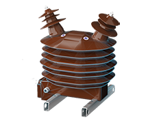
The mounting position of the instrument transformers CTS, CTT and CTB is arbitrary. The transformers CTSO 38 are mounted in the vertical position.
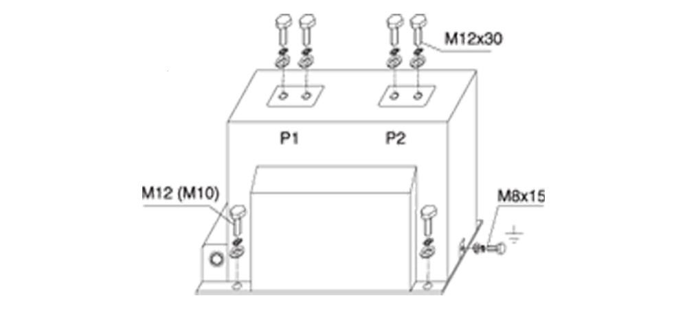
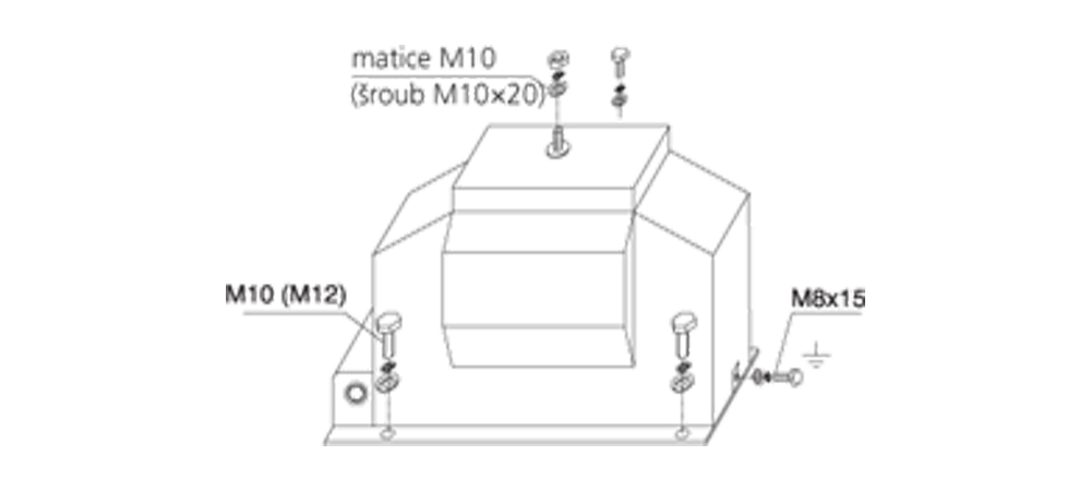
The transformers are fixed by the means of four screws M10 (CTS 12) or M12 (CTS 25, CTS 25X, CTS 25X Sch,CTS 38, CTS 38X, CTS 38X Sch, CTSO 38, CTB 25, CTT 25) in the holes in the basic plate or in the profiles.The connection of the power circuit to the primary terminals is done by the means of the screws M12 (See picture No.1) with max. torque module 70Nm.We recommend use terminal ends corresponding to the used cross-section of the conductor (its maximum size is 10 mm2) for attaching to the secondary outlets.Metal functional parts of the transformer are coated against corrosion. The primary terminals are galvanized with nickel or silver-plated. The secondary terminals are galvanized with nickel. The basic plates are cold galvanized (transformers for the indoor settings) or hot galvanized (transformers for the outdoor settings).
We recommend clean transformers from dirt and draw close the connections in case of shut down.
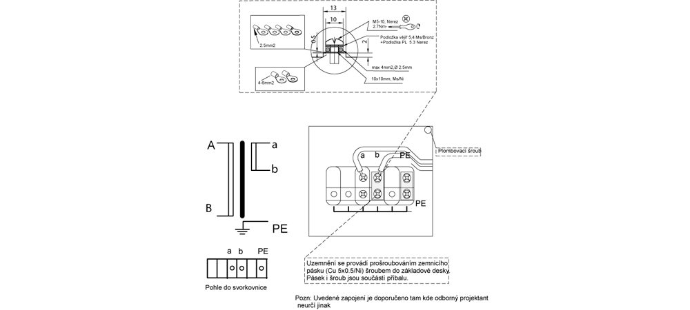
Before starting-up it is necessary to earth the metal base of transformer (earthling “cube” with screw M8x15 with max.
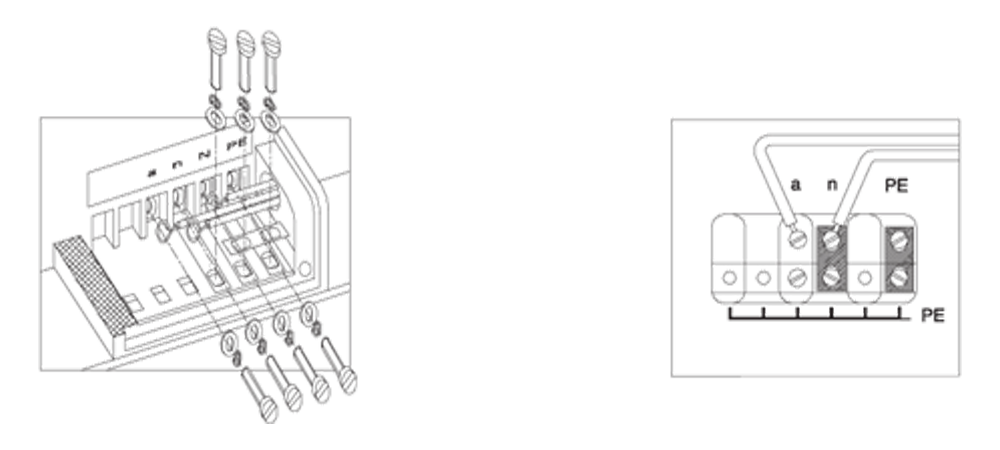
torque module 10Nm see picture No. 1) and one secondary terminal of every outlet (See picture No. 2). The secondary
outlets, that were not used, are necessary to be short connected and earthed (See the examples in pictures No. 3-5).The
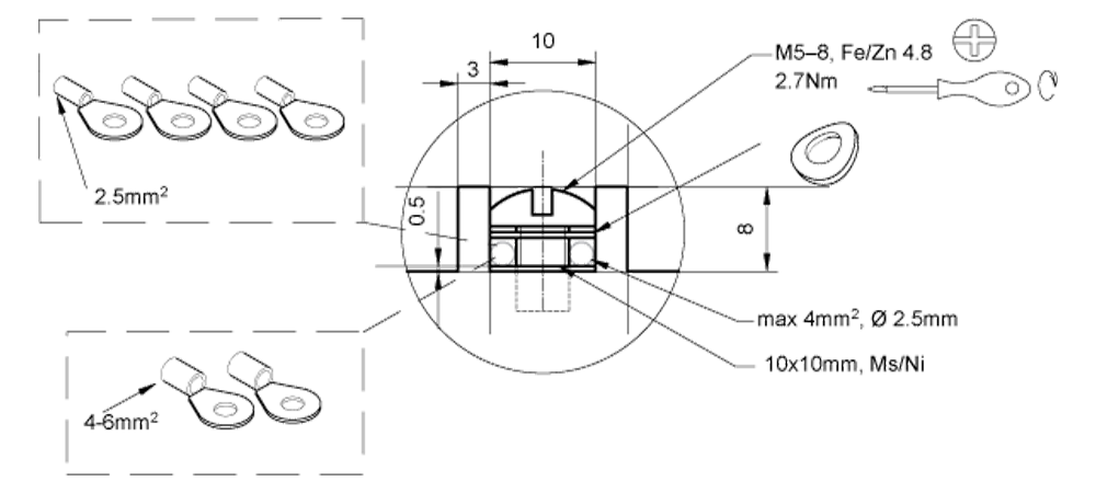
earthling of the secondary outlets is done by the means of screws M5x16 (max. torque 2.7 Nm) and jumpers (See picture No. 2) that arethe parts of the set of each supplied transformer.
:
Pic. 1 Mounting system of transformer CTS
Tightening torque max.
Primary terminal M12 70 Nm
Ground terminal 10 Nm
Secondary terminal M5 2.7 Nm
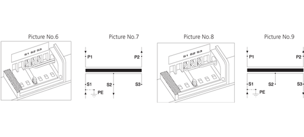
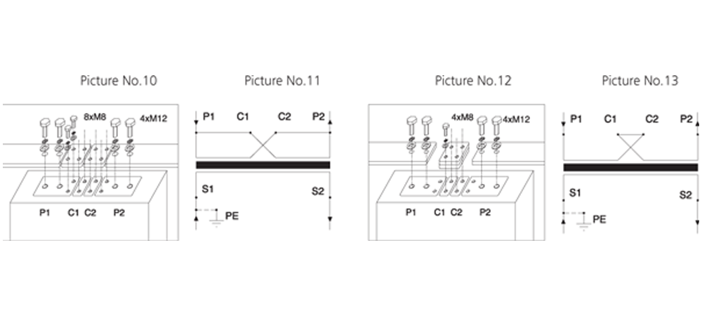
The construction of transformers allows the switching of the ranges on both the secondary and primary sides. The secondary switching is made by the means of switching of branches on the secondary coil. See the examples in picturesNo. 6-9. The primary switching has easy mounting, connecting two jumpers into the circuit by the means of screws M8 (both the screws and jumpers are the part of the set of the transformer). See the examples of interconnection inpictures No. 10-13.
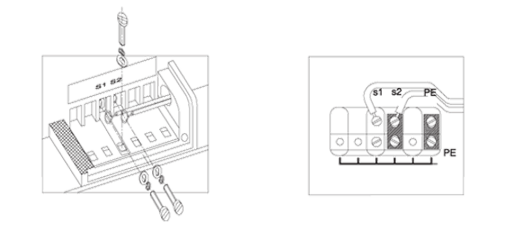
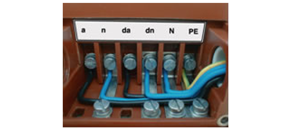
Pic. 2 The way of connection of conductors to the secondary terminals, including of the earthing of one terminal for the transformers for the indoor and outdoor settings
The secondary terminal board is provided with the plastic cover with sealing cover and also, on the sides, with the threads Pg16 with screwed blinding and jumper for the drawing die of the secondary line-wires.The secondary terminal board of the transformers for the outdoor settings (type CTSO) is provided with the waterproofcover with sealing screw and waterproof bushing for the connection of the secondary line-wires.
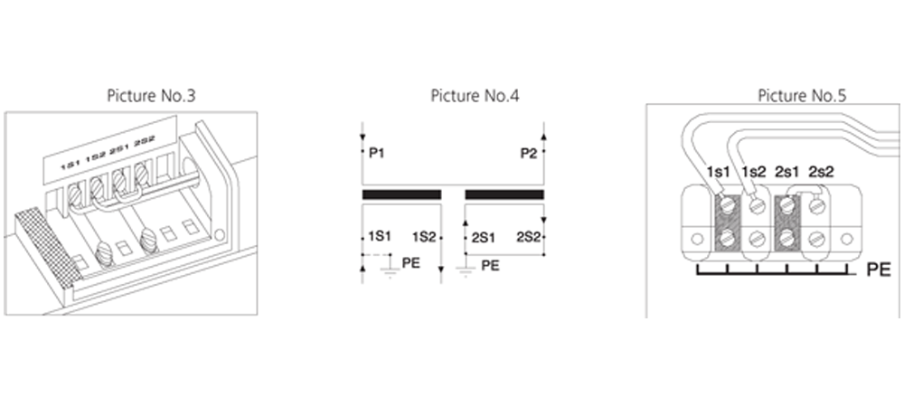
The examples of circuit of the secondary terminal board of measuring current transformers, including special cases
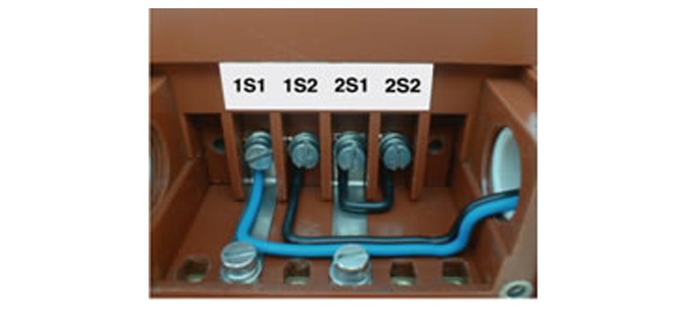
There is the example of circuit of two-cored transformer with ratio 50//5/5 A in the picture No. 3. The terminals of the fi rst secondary winding (symbols 1S1 and 1S2) are connected to the external load and one terminal (in this case 1S1) is earthed. The second secondary winding (symbols 2S1 and 2S2) is not connected to the external load and so the terminals have to be interconnected in the short circuit and they have to be earthed. The wiring diagram is in picture No. 4. The mounting of the terminal board is in picture No. 5.
The example of mounting of the secondary terminal board of one-core transformer with the ratio 50-100//5 A and with the
switchingon the secondary side you can see in the following pictures. Picture No. 6 describes the connection for the ratio
50//5 A. Terminals S1 and S2 are brought out to the external load and one terminal (in this case S1) is earthed. The electric
scheme is in picture No. 7. The mounting for the ratio 100/5 you can see in picture No. 8. Terminals S1 and S3 are brought
out to the external load and terminal S1 has to stay earthed. Terminal S2 remains unassigned. Wiring diagram is in picture No. 9.
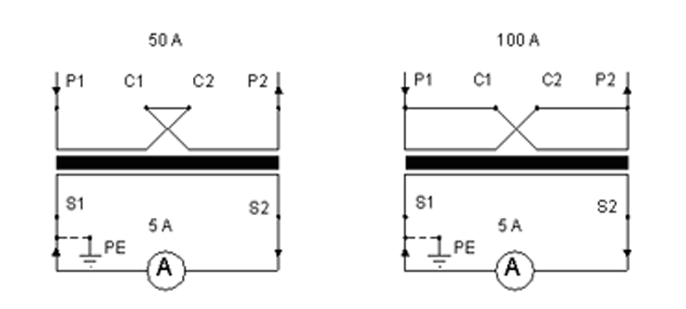
In the following case you can see the example of mounting of the primarily switchable transformer with the ratio 50-100//5 A. In picture No. 10 is shown the connection for the primary current of 100 A. Terminals P1, C1 and P2, C2 are interconnected by the means of the special connector and screws M8. Wiring diagram is in picture No. 11. The way of contacting for the primary current of 50 A is in picture No. 12. Terminals C1 and C2 are interconnected by the means of both connectors and screws M8. Scheme is in picture No. 13.
Note: The above-mentioned connections are recommended by the producer only in the caseswhere the expert designer does not determine other way.
Secondary terminal:

The Instruction for the voltage transformes
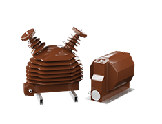
The mounting position of the instrument transformers VTS and VPT is arbitrary. The transformers VTO and VPT are only mounted in the vertical position. The transformers are fixed by the means of four screws M10 (VTS 12 and VTD 12) or M12 (VTS 25, VTS 38,VTD 25, VTO 38, and VTDOR 38) in the holes in the basic plate or in the profi les. The connection of high voltage to the primary side is recommended by the means of the terminal ends with 10 mm and screws M10 with max. torque module 20Nm. The example of mounting system of transformer is shown in picture No. 1 (VTS 12). For the contacting on thehigh voltage side of transformers with isolators we recommend to use the conductors of maximum diameter of 6 mm2 and terminal ends by the reason of springing of the dynamic forces within the system.
ATTENTION! The isolators must not be pre-stressed mechanically in the direction away from the body of transformer during the mounting process.
We recommend clean transformers from dirt and draw close the connections in case of shut down.
Before starting-up it is necessary to earth the metal base of transformer (earthling “cube” with screw M8x15 with max.torque module 10Nm see picture No.1).
Pic. 1 The example of mountingsystem of transformer (VTS 12)
The earthling of the secondary outlets is done by the means of screws M5x16 (max. torque 2.7 Nm) and jumpers (See picture No.2) that are
the parts of the set of each supplied transformer. The example of mounting is shown in picture No. 2.The construction of transformers allows the switching of the ranges on the secondary branches of transformer. The examples are shown on the following page. The secondary terminal board is provided with the plastic cover with sealing cover and also, on the sides, with the threads Pg16 with screwed blinding and jumper for the drawing die of the secondary conductors.The secondary terminal board of the transformers for the outdoor settings (types VTO and VPT) is provided with the waterproofcover with sealing screw and waterproof bushing for the connection of the secondary conductors.
ATTENTION! It is necessary to check after each starting-up whether the secondary winding is not earthed by one terminal on the terminal board and by the second terminal by the outlet in the low voltage part. Otherwise the instrument is connected in short way and after the starting-up of high voltage the destruction of the instrument occurs.
Pic 2. The way of connection of the secondary outlet and outlet of primary winding in earth of indoor and outdoor type of VTS and VTO
The examples of circuit of the secondary terminal board of measuring voltage transformers,including special cases
Single-pole instrument transformers of type VTS for the use of three-phased, inefficiently earthed systems are usually provided withtwo secondary windings. The first of these windings is used for the measurement or protection, the second for signaling of earthconnection. They are linked up in three phases – the primary and secondary windings are star-connected, auxiliary winding in open triangle (See wiring diagram in picture No.3).
Terminal “N” of the primary winding, one terminal of the secondary winding and one of the end terminals of the open triangle have to be earthed during the operation. (ATTENTION! In case of earthling of the open triangle on two terminals there is the danger of instrument destruction.) The example of circuit of terminal board is shown in picture No. 4.
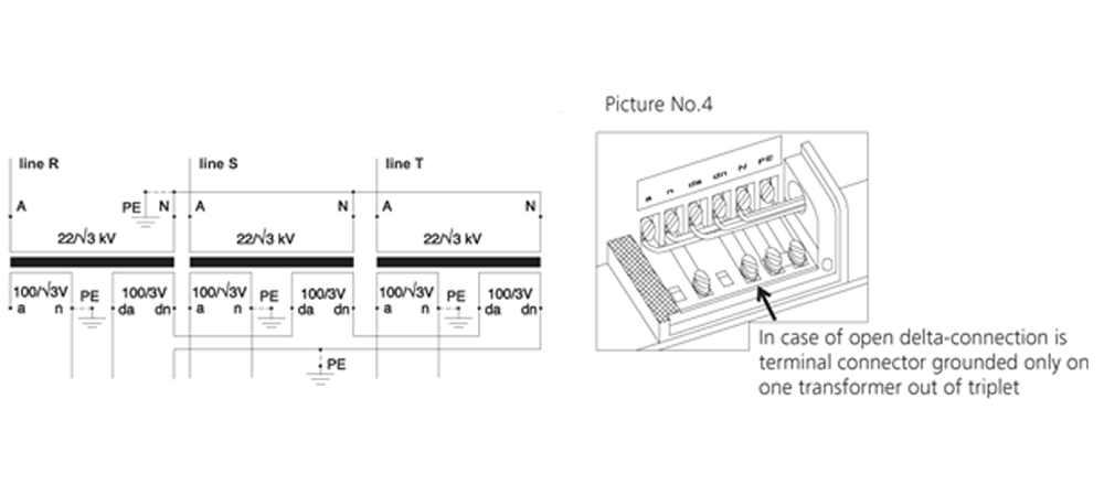
Pic. 3 Wiring diagram of triple of single-poled transformers
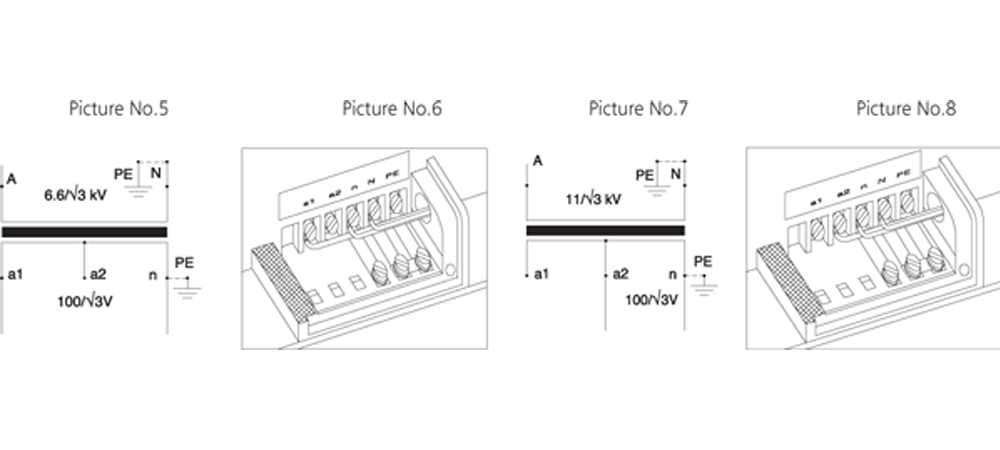
In the following case you can see the example of switchable single-poled transformer with the ratio 6600-11000/√3//100/√3 V. The switching is possible due to branch on the secondary winding. Picture No. 5 shows the scheme for the ratio /√3//100/√3 V. The measuring outlet is between the terminals a1 – n, terminal a2 remains unassigned. The mounting of terminal board is shown in picture No. 6. The scheme for the ratio 11000/√3//100/√3 V is shown in picture No. 7. The measuring outlet is here between terminals a2 – n, terminal a1 remains unassigned. The mounting of terminal board is shown in picture No. 8.
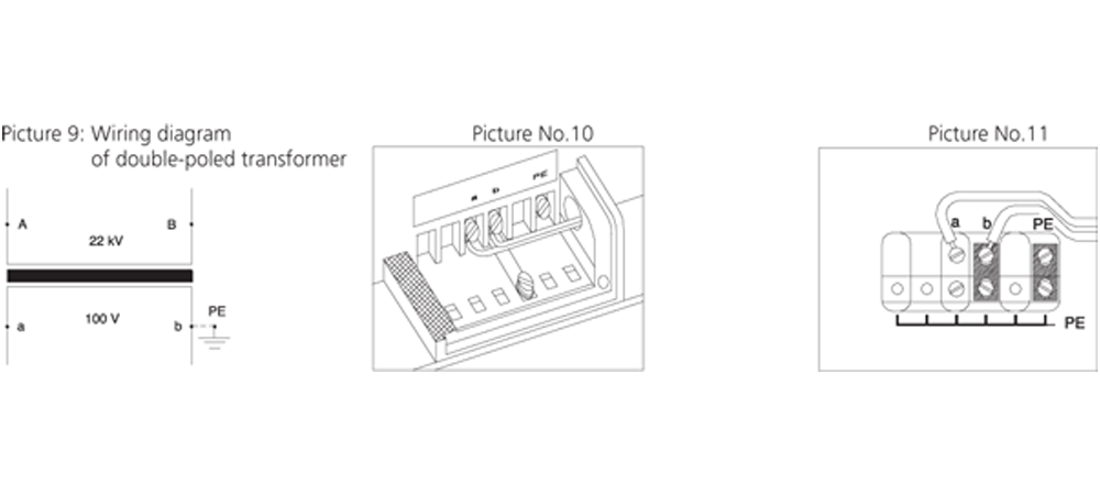
Double-poled instrument transformers VTD and VPT have all parts of primary winding, including terminals, isolated from earth. The isolation is dimensioned on the level of testing voltages according to the corresponding nominal voltage.One of the secondary terminals must be earthed during the operation (it is not the case of the so called “V- connection”).
Wiring diagram of transformer is shown in picture No. 9. The connection of terminal board for indoor setting is shown in picture No. 10 and for outdoor setting in picture No. 11.
Note: The above-mentioned connections are recommended by the producer only in the cases where theexpert designer does not determine other way.
Secondary terminal:
The Instruction for the voltage transforme VPT 100
Connection
The connection of the regulating source and transformer VPT 100 is done according to the following diagram:
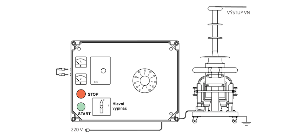
Pic. 1 VPT 100 scheme
We insert interconnection in the side-wall of regulator REG 100 or we connect the end switcher of the inlet door of the area of high voltage.
We interconnect the cable leading from transformer and the regulator (non-typical socket of 380V). We make earthling of transformer (there is earthling connector M8 on the skeleton of instrument). We connect the outlet of high voltage with the tested object. We connect the ending of the lead-in wire in the socket of AC 220V.
Description of handling
We switch on the supply from the source of 220V with the switch “Main switch”. We turn the button of regulator at the value of “0”. We switch on the green button “START”. The signal red bulb will switch on. The red bulb informs the personnel about the state under the voltage. We turn continuously the button of regulator to the right and we increase the voltage on the output of transformer until we reach the required level. During this process we can see on the panels of instrumentscurrent demand and the level of exciting voltage. When we overstep the current 14A (it is 3kVA) the protection A15 starts and disconnects transformer from the excitement within the moment. (The red bulb will switch off.) For the restarting of the function it is necessary to turn the regulator button to the value of “0” and to push the button “START”. The red button “STOP” is for the disconnection of the source of excitement. After fi nishing the operation of the instrument we recommend to switch “Main switch” off, to turn the button of regulator to the value of “0” a to earth the high voltage outlet of transformer
Safety of work
The instrument can be operated only by the person that fulfi lls the rules of regulation 50/1978. At the same time this person must follow the instructions for the work in the testing laboratories of high voltage.

:
Pic. 2 Scheme of transformer
The Instruction for the voltage transformes VPPT 38.2
The appliance transformer VPPT 38.2 shall be installed in the position with its epoxide body above the metal foundation sections.
The transformers are fixed with four screws M12 by the holes in the foundational sections. We recommend connecting of HV on the primary side by means of cable lugs of a diameter of 10 mm and screws M10 of a max. tightening torque of 20 Nm. In case of a shut-down we recommend cleaning of the transformers from rough dirt and tighten the joints.
Before putting the transformer into operation it is necessary to earth the metal sections of the transformer (earth screw M8x15 with a max. tightening torque of 10 Nm).
Earthing of secondary outputs is done by means of screws M5x10 and jumpers, which are included in the delivery of every transformer. Connection to the secondary leads is provided by means of cable lugs (for the 10mm2 wire, they are included in the accessories). An example of installation is in Fig.1.
The secondary terminal block is fitted with a water-resistant IP 65 cover with a sealing screw and water-resistant bushing Pg21 for connection of secondary conductors.
All components of the primary winding of appliance transformers VPPT, including terminals, are insulated from the earth. Insulation is dimensioned for the level of test voltages according to the corresponding rated voltage.
During the operation, one of the secondary terminals must be earthed (this does not apply to so-called V-connection).
Note: The described connections are recommended by the manufacturer to be used only where the professional project engineer does not specify otherwise.
Smart Load AFR 30
The AFR 30 Smart Load is an instrument designed to protect metering voltage transformers against adverse effects of ferroresonance in high voltage power distribution systems with ungrounded or indirectly grounded neutral wire. Unlike other methods, it is targetedly enabled only when ferroresonance occurs, being passive in common operation or with nonsymmetrical loads or single-phase ground connection, which means it does not load the metering system.
Ferroresonance comes up between transformer inductance and conductor or switching element capacitance. Connecting, disconnecting, ground connection or other transitional effects may be the trigger events. Ferroresonance oscillations cause significant overvoltage and current surges as a result in very high transformer magnetic circuit saturation. This most often leads to metering transformer destruction.
AFR30 Smart Load acts as metering voltage transformer protection against such effects. Unlike other methods, it is targetedly enabled only when ferroresonance occurs, being passive in common operatin on with nonsymmetrical loads or single-phase ground connection, which means it does not load the mettering system.
Nominal voltage 100 – 200 VAC
Insensitivity window 0 – 20 VAC
Coverage IP20
Overvoltage class II
Climate class 5 / 50 / 40
Operating temperature -20°C až 40°C
Storage temperature -20°C až 70°C
Maximum humidity 95 % non-condensing
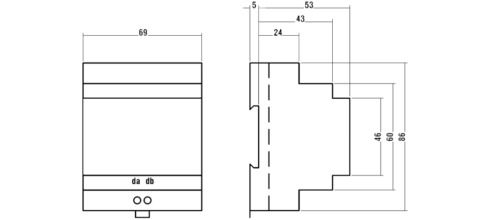
Dimensions 69 x 86 x 58 mm
Mass 0,05 kg
Material of cover polycarbonate
Instalation on 35 mm DINstrip in compliance with DIN EN 50 022
Connection terminal bar, wire cross section 0.5 to 2.5 sq mm

Wireup
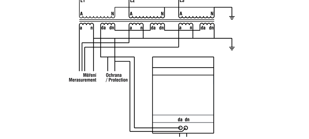
AFR30 works in conjuction with a mettering voltage transformer while open delta is connected to auxiliary windings (terminals da, dn). Metering winding wiring is not changed. The open delta configured auxiliary windings may be, together with AFR30 Smart Load, used for ground connection protection relay, which is to be connected parallel to AFR30 using the protection relay manufacturer’s recommendations. AFR30 parallel connection does not affect protection relay operation.
AFR 30 Smart Load is usually installed in the measuring and protection control panels. The instrument is designed to be installed on a 35 mm DIN strip. 2.5 square millimeter copper wire is recommended for the circuit.
Smart Load wireup diagram in metering voltage transformer auxiliary winding open delta configuration
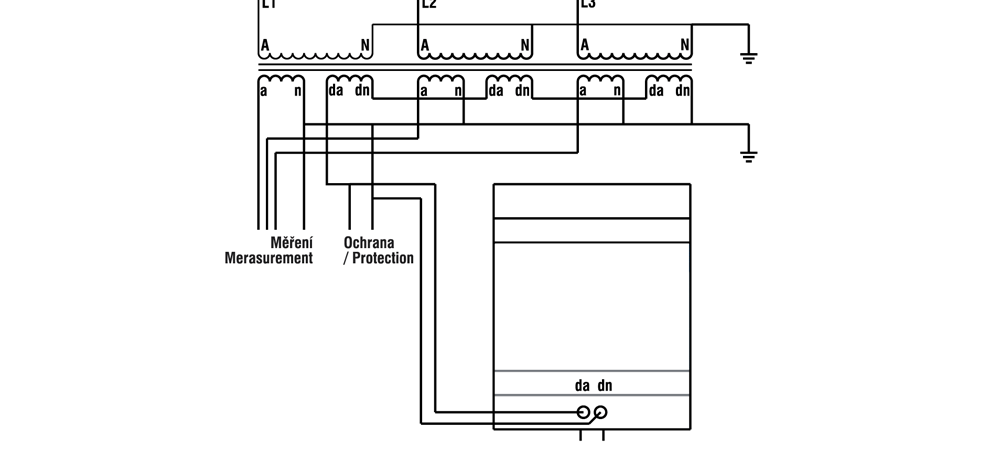
A, N: Metering transformer high voltage terminals
a, n: Secondary metering winding
da, dn: Other secondarywinding terminals
AFR30: Smart Load
symbol PE PE
Smart Load to AFR 30 Reduce Ferroresonance
The AFR 31 Smart Load is an instrument designed to protect metering voltage transformers against adverse effects of ferroresonance in high voltage power distribution systems with ungrounded or indirectly grounded neutral wire. Ferroresonance comes up between transformer inductance and conductors’ or switching elements’ capacitance. Connecting, disconnecting, ground connection or other transitional effects may be the trigger events. Ferroresonance oscillations cause significant overvoltage and current surges as a result of transformer magnetic circuit saturation. This most often leads to metering transformer destruction.
AFR 1 Smart Load acts as metering voltage transformer protection against such effects. Unlike other methods, it is targetedly enabled only when ferroresonance occurs, being passive in common operation or with nonsymmetrical loads.
Magnitude of trigger voltage can be adjusted to 20, 25 or 30 volts. For selectivity with ground connection protection devices an activation time delay circuit (4 seconds as default) is used. This is suitable at installations where a voltage transformer is used not only for measuring but as power supply for protection devices too (ground connection detection, automatic reconnection circuits etc.).
The AFR 31 is designed to be installed on a 35-millimeter DIN strip (DIN EN 50 022).
The AFR 31 works in conjunction with a metering voltage transformer while open delta is connected to auxiliary windings (terminals da, dn). One of pole must be grounded. Before connection. The open delta configured auxiliary windings may be, together with the AFR 31 Smart Load, used for ground connection protection relay, which is to be connected in parallel to AFR 31 using the protection relay manufacturer’s recommendations. AFR 31 parallel connection does not affect protection relay operation.
Nominal voltage 100/3, 110/3, 120/3 VAC
Activation voltage no jumper 20 VAC
3+4 jumper 25 VAC (default)
1+3 jumper 30 VAC
Activation delay 4.0 sec (other value in range 0.5 ÷ 10sec on request)
Protection degree IP20
Overvoltage class II
Climate class 5 / 50 / 40
Operating temperature -20°C ÷ 40°C
Storage temperature -20°C ÷ 70°C
Maximum humidity 95 % non-condensing
Dimensions 69 x 86 x 58 mm
Mass 0,05 kg
Material of cover polycarbonate
Instalation 35 mm DIN bar mount (DIN EN 50 022)
Connection screw terminals, 0.5 ÷ 2.5 mm2 wire cross section
Wireup
Desired activation voltage must be set before installation. Release snap-in latches with an appropriate size screwdriver and remove the instrument cover.
You can set on of three levels according technical parameters table. Default activation voltage level is preset to 25 V. Higher level is suitable for high voltage grids with higher unbalance of parasitic capacities. After setting, and snap in the rear panel back (keep attention to the correct LED light pipe position).
The AFR 31 is designed to be installed on a 35-millimeter DIN strip (DIN EN 50 022) and for indoor use only.
Natural air circulation should be provided inside the distribution board cabinet, and in the instrument’s neighborhood, especially underneath the instrument, no other instrumentation that is source of heat should be installed. The instrument must be installed in indicated position with its terminals oriented down, usually in the measuring and protection control panels.
The AFR 31 works in conjunction with a metering voltage transformer while open delta is connected to auxiliary windings (terminals da, dn) as shown in the wiring diagram below. 2.5 square millimeter copper wire is recommended for the circuit. One of pole must be grounded. Before connection, check the grounding both at the transformer and the load side to avoid unwanted duplicity; otherwise measuring voltage transformers can be short-circuited and destroyed.
The open delta configured auxiliary windings may be, together with the AFR 31 Smart Load, used for ground connection protection relay, which is to be connected in parallel to AFR 31 using the protection relay manufacturer’s recommendations. AFR 31 parallel connection does not affect protection relay operation.
Smart Load wireup diagram in metering voltage transformer auxiliary winding open delta configuration
Connection of instrumental voltage and current transformers
KPB Intra s.r.o.
Ing. Josef Stejskal
Experience with connection of instrument transformers indicates that not every installation company is completely clear on how to connect the converter in practice. Examples of correct connection, potential errors and their prevention are described below.
Instrument voltage transformers
It applies generally that a voltage transformer may not be operated till a short circuit and, if it takes place, an explosion follows very shortly after it. The explosion results in consequent damage of adjacent equipment.
Connection of three earthed transformers with one measuring and one auxiliary winding should be done in accordance with the diagram in Fig. 1. Voltmeters are connected to the measuring windings (100/√3 V). One of the terminals is always earthed (“n” terminal here).

:
Pic. 1
:
Pic. 2
The auxiliary winding (100/3 V) is connected in a so-called “open triangle”. Unlike the preceding case, earthing is done at only one point here. For an example of connection in practice please see Fig. 2.
One of the errors of installation companies is earthing of an open triangle similarly as in the case of the measuring windings, i.e. one of the terminals of the secondary circuit is connected to the earth. However, earthing of not only the “da” terminal but also the “dn” terminal takes place here with respect to the character of connection and the transformers are operated until a short circuit occurs. An explosion occurs consequently.
Insufficient checking is another error that appears in practice. There are cases where one installation company performs connection of the measuring winding of transformers in accordance with Fig. 1, i.e. it applies earthing of the “n” terminal. This company only performs installation of transformers. Another company will connect voltmeters and use their earthing terminal for earthing. However, this terminal has already been connected with the “a” terminal of the transformer through the supply line. General connection is not verified by anybody. The instruments then operate until a short circuit occurs and an explosion is a matter of several seconds.
Instrument current transformers
A certain advantage of installation of current transformers is the fact that explosions do not occur in the case of an error in connection; however, damage of the instrument or risk for the operator may also occur here.
It applies generally that the secondary outlets are either connected to the burden or interconnected to the short circuit and one of the outlets is earthed. This principle is apparent from Fig. 3 and Fig. 5. Several errors are made in practice. Non-earthing one of secondary terminals may be one of them. Capacitive coupling is created then and the secondary circuit emits sparks on the frame. Conductive paths are created in the case of longer duration.

:
Pic. 3

:
Pic. 4
Ambiguities with the switch-over type of transformer can be another source of errors. A correct example of connection is illustrated in Fig. 4. It is apparent here that one terminal always remains free. An error occurs if this terminal is earthed. The transformer stops measuring then.
The above described errors may be prevented using several methods. Primarily, installation must be carried out by competent persons with practise in the given field. If they have not required experience, they must study installation instructions attached to each instrument or catalogue documentation (see “Operation and installation instructions”). It is also necessary to perform inspection of a general circuit, i.e. not only operations performed by each individual company, but connection as a unit and its compliance with the design. After all, disconnection of wires and then measuring with an ohmmeter is sufficient for verification of earthing of terminals and burdens.
Practical experience with installation of converters, potential errors and methods of their rectification are described above.
We hope to contribute to understanding of issues and prevention of consequent potential damages by giving the explanation above.
:
Pic. 5
Protection of voltage and transformers against ferroresonance
KPB Intra s.r.o.
Ing. Josef Stejskal
The phenomenon of „ferroresonnance “ can occur in single –pole voltage transformers in HV inadequately earthed cable
networks. The impedance of transformer and the earthing capacity of the cable create a potentially oscillating RLC circuit.
When an overvoltage come by the case of earth connection or some switching, the phenomenon of ferroresonnance can
appear. The consequences are overheating of magnetic core and coil, damage of insulation and burst.
To prevent HV equipment we recommend to use connection of dump resistor in open delta of additional secondary windings
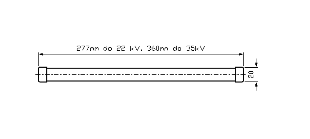
(see picture 12 below). Mounting dimensions are in the picture 13. The value of resistance is 68 Ohm/ 200W (type
of TR305 producer is „ Tesla Blatná“).
Resistor is available to order in our firm and we can deliver it single or with other
transformers. We recommed to use it in new installations as prevention.
We hope to contribute to understanding of issues and prevention of consequent potential damages by giving the explanation above.

:
Dumping rezistor 68 Ohm /200W

:
TR 305 68R/J, H5 and TR 305 68R/J, V2
Ferroresonance is still relevant
KPB Intra s.r.o.
Ing. Josef Stejskal
The phenomenon called “ferroresonance” has already been described in many publications. For the uninitiated, it may be briefly stated that this involves a phenomenon found in electrical networks, where resonance occurs between an induction transformer and a capacity main. We shall leave aside a more detailed explanation for now (for those interested, the necessary information may be obtained on the Internet). It must be said, however, that resonances are harmful to high voltage equipment and often lead to permanent damage. As manufacturers of metering transformers, we therefore feel obligated to draw attention to the relevance of the given problem.
Experience from recent years has been referenced in frequent responses to customers at which interruption of a current metering transformer has occurred in connection with the replacement of older electromechanical electrometers with new electronic ones. In principle, such an exchange should not cause any difficulties, but when we think more deeply about this, unwittingly, greater susceptibility to ferroresonance may occur. The essence is that the new electronic electrometers have an internal load substantially lower than the original electromechanical system. This leads to so-called “stress reduction” of the transformer and subsequently to a decrease in the dampening effect of possible resonances.
To this actuality, often this leads to a frequent psychological error by designers. It has long been the experience of the human subconscious where professional dimensioning is unknown. In the field of current metering transformers (CMT), this occasionally leads to a requirement for higher outputs in relation to the degree of precision without any justification. Here, however, it is necessary to note structural links. Dimensioning of a transformer for higher output may be none other than increasing the dimensions, both the primary as well as the secondary conductors and by decreasing both active resistances. The result is evident in the decrease in the dampening effect of ferroresonance.
Another reason for the susceptibility to ferroresonance is the lack of communication from the side of the customer, i.e. designer, users… The origin of this situation is again in human psychology. Because, for example, if this leads to damage to the CMT even after several replacements, according to business logic, the transformer is always to blame. According to lay reasoning – how could it be otherwise, particularly if the equipment is still within the warranty period? According to experience with business rules, most dealers therefore select the method in which “it is necessary to submit a claim without describing the relationships of the equipment and with the conviction that if the manufacturer refuses the claim we will turn elsewhere”. But the question is put forth as to whether such a procedure actually resolves the problem. The opinion of our manufacturers of this equipment is that this isn’t entirely certain. Many customers, after numerous interruptions of the CMT under specific circumstances, admit that this or that installation point is actually problematic, that there were already problems with overvoltage and the breakdown occurred in other components (absence of safeguards). I write about this primarily to emphasize that technical problems must always be resolved by only technical means. For a successful resolution, a manufacturer needs to be informed about all the circumstances, on principle in advance.
If we notice that problems have already occurred somewhere, which are marked by the occurrence of ferroresonance, we recommend several solutions:
1. One is the universally known connection of dampening resistance in the perimeter of an open triangle helped by coiling, see details at www.kpbintra.cz.
2. In other cases (particularly at railways), we propose transformers with a lower saturation of the magnetic perimeter. Such instruments are larger and more expensive, but their resistance to resonance compensates for the costs related to removal of defects from previous designs.
3. In other cases, particularly in open pit mines, reinforcing the insulation of the primary coiling is beneficial after adapting the other parameters of the machine.
From the aforementioned, it is apparent that the problem of ferroresonance is still relevant in electrical networks.
Experience shows that designed technical solutions have demonstrated their reliability over the years. The solution, however, has always been reached after mutual communication with the manufacturer.
Fuses for high voltage measuring transformers
KPB Intra s.r.o.
Ing. Josef Stejskal
Use of fuses for voltage transformers is a long-term custom supported by rich experience. A fuse is a protective element that ensures transformer disconnection from network circuits by switching off the currents exceeding the rated value. Switching off a current usually results from a defect of the insulation system of the transformer; however, transient phenomena and ferro-resonance currents also cannot be excluded in many cases. The fuse usually switches off upon bursting of the transformer and development of an electric arc. It means that the function of fuses consists in protection of the surroundings against destructive effects.
High voltage current protections are the new protective component. In KPB Intra they are produced in two-type dimensions into electric system up to 22kV and also for 35kV (picture 5). Rated current protections are 32,50 and 80mA. High voltage will be switched off and disconnected at their exceed. Current protections position predetermines their higher sensitivity for overcurrents than at current fuses. Their contribution is faster frequent disconnection often before its explosion.

:
Pic. 1

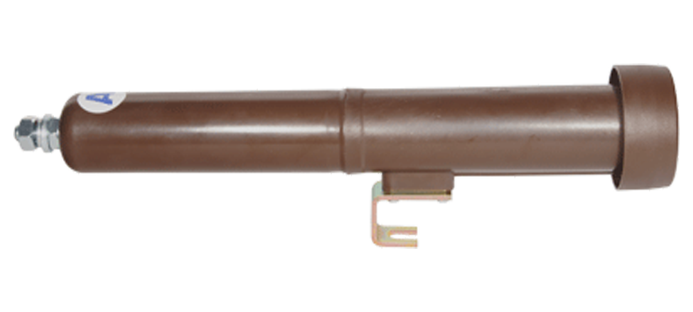
:
Pic. 2
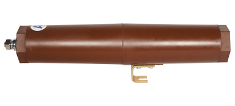
The company offers application of fuses in transformers in several modifications, e.g. Fig. 1 shows a fuse in the horizontal position with an outlet in its axis. A fuse in the horizontal position with an outlet in the vertical axis of the transformer is another variant, see Fig. 2. The third method is represented by a vertical fuse in the axis of instrument high voltage with the outlet on a cable, see Fig. 3. Fuse carriers are located in epoxy casing. Connection to the transformer high voltage terminal is made by means of a screw; lug type thread is illustrated in Fig. 2.

:
Pic. 4
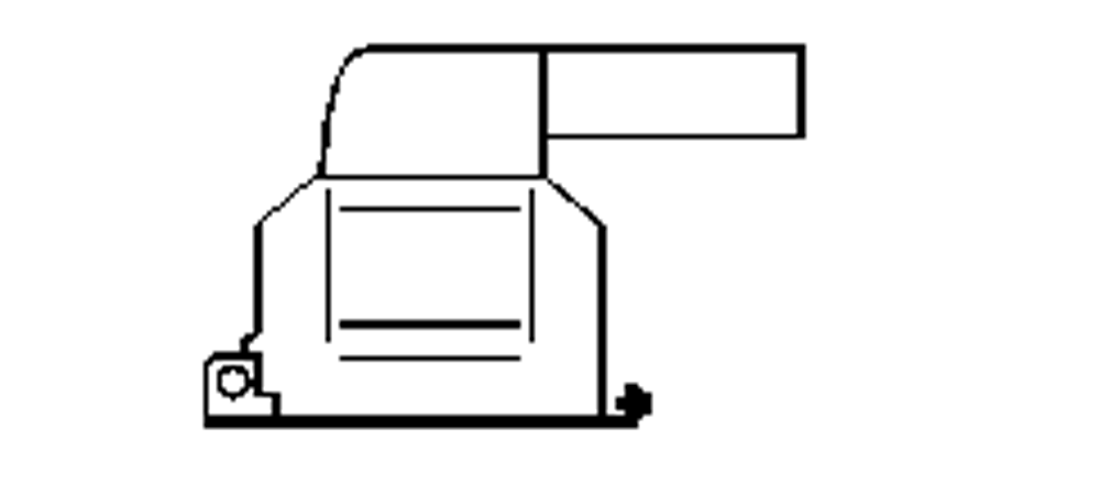
:
Pic. 5

Pic. 3
VTS38 transformers for 35 kV networks illustrated in Fig. 4 can be fitted with fuse 3.15A supplied by BRUSH. This concept is identical to the case illustrated in Fig. 3. Individual methods of design arrangements have resulted from requirements of the customers. Specific dimensions form a part of company documentation and can be sent upon request.
In conclusion it is possible to say that we definitely recommend fuse preselection and transformators protection.
:
Fuse holder KPB 25 Epoxide
:
Fuse holder KPB 25 Platic
Degrees of precision in current instrument transformers
KPB Intra s.r.o.
Ing. Josef Stejskal
The following article discusses the characteristics of current metering transformers (hereinafter CMT) in relation to the occurrence of a broader demand from customers.
In recent years, the problem of continuously larger variability has arisen in the collection of electrical energy in connection with alternating day and night or even in seasons (summer, winter, etc.). The interest of distributors and collectors of electrical energy is the most accurate metering in a relatively broad scope. At CMTs, switching design has been used in practice, which enables the use of two nominal currents where the higher current, as a rule, is two times lower. Another principle is a transformer with a single nominal current, but the structural materials enabling a broad scale for metering are defined by the so-called “S” class (special). Below is a description of the principle of switching, the degrees of metering a switchable version and comparing it with the “S” class. Current switching is performed either on the primary or the secondary side. On the secondary side, this is structurally simpler and current switching is resolved by a turn in the secondary coiling. The method for connecting is apparent from the diagram in fig. 1 (design 50-100//5A).
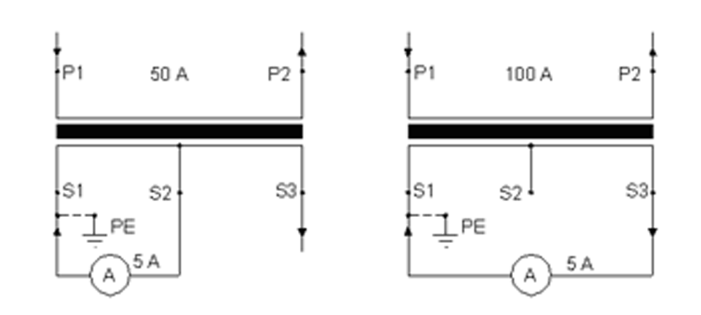
:
Pic. 1
:
Pic. 2
Primary switching is conducted by a serial (for lower current) or parallel connection (for higher current) in sections of the primary coiling, see fig. 2. The advantage is the achievement of short-circuit classes relative to the switched current (a lower current has a cross-section of coiling determined by a profile section while a higher current has a cross-section of the coiling two times the profile section). In comparison with the first method, this is more difficult in production, which will have its own effect on the final price.
The degree of precision of both switchable versions is provided by the standard ČSN EN 600 44-1 and is noted in fig. 3. From the image it is apparent that the required degree of precision of 0.5% is maintained in the field of 100 to 120% of nominal current both at lower as well as higher current switching (noted by a dark marks in the blue field). The precision corridors are then spread out in the direction toward smaller currents (black lines) so that at 20% current, precision achieves 0.75% (simply stated precision deteriorates).
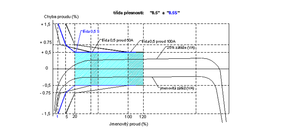
Pic. 3
The relatively small degree of precision in the switchable design is assumed by the “S” class (special). According to the aforementioned norms, precision is guaranteed in the range from 20 to 120% of the nominal current. On the graph, corridors are marked by a dark blue line and the precision field is light blue. When ordering, this is stipulated as “0.5S”. If we compare the price of switchable versions with the “S” class, it is possible to state in general that the “S” class is less expensive by the difference related to the value of the primary current. Another significant advantage of the “S” class is the fact that it is not necessary to switch and conduct related installation work linked to the contracted switching of high voltage in advance.
In conclusion, there is little left than to recommend the “S” class as the design with a more universal application at a reasonable price.
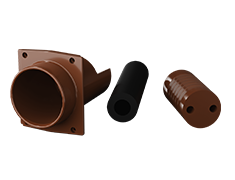
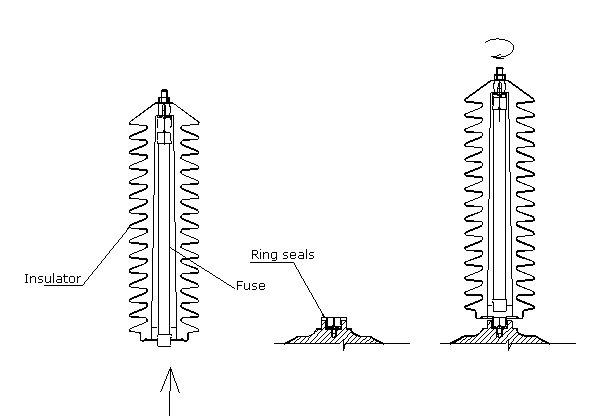
Assembly of insulator with fuse – VTO 38P
- We put the fuse into the epoxy insulator and insert it into the contact.
- The fuse has to be centred to the middle of the cavity.
- Then we put the ring seals on the thread part of transformer body.
- We check the thread and possibly remove the dirt.
- We screw the insulator with the fuse very carefully and tighten it by hand.
When installing the thread, we take care not to screw beyond the thread. Tighten the thread within the elasticity limits of the seal. The thread must not be stripped!
The Instructions for the secondary LV fuses
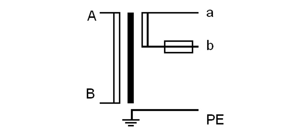
Fusing on the secondary side of the transformer is used in the event of a short circuit in the secondary winding. A short circuit in the secondary winding can occur, for example, due to improper connection of the secondary winding or cable interruption. In response to this, a transformer with a low-voltage (LV) fuse (Fig. 1) incorporated into the secondary winding (Fig. 2) was designed.
:
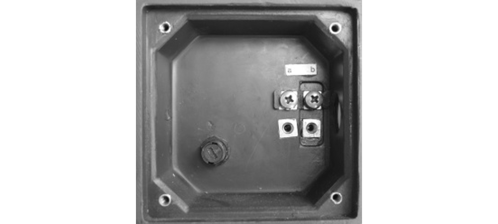
Pic. 2A Terminal block VPT 25 with secondary fusing
:
Pic. 2B Scheme of diagram
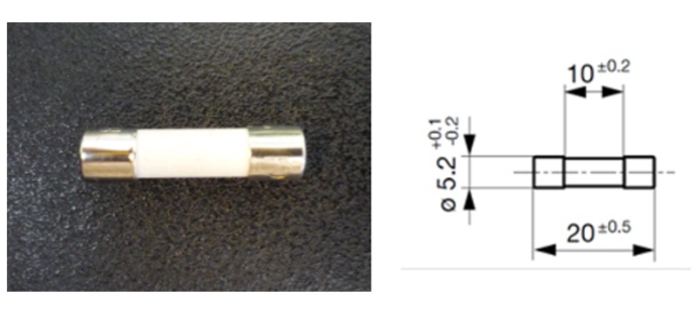
Pic 1. Low voltage instrument fuse
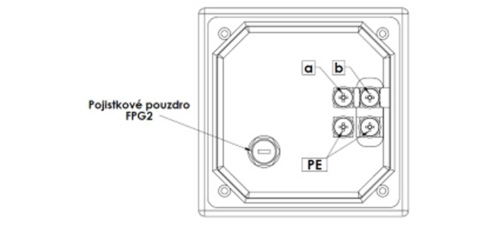
Assembly procedure
The image shows a secondary terminal block with the FPG2 fuse casing.
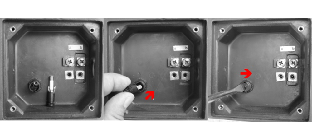
The fuse is removed using a screwdriver. The screwdriver must have a head size of no more than 1×5 mm. Insert the screwdriver into the slot in the fuse casing and turn it to the left. This releases the fuse cap with the fuse inside, which can then be easily removed by hand. After that, the LV instrument fuse within the fuse cap is easily replaced by hand.
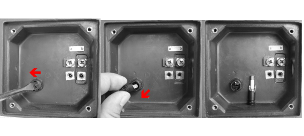
Following the manual replacement of the LV instrument fuse in the fuse cap, the cap is easily reinserted into the fuse casing by hand. A screwdriver is then inserted into the slot. The screwdriver must have a head size of no more than 1×5 mm. The fuse is secured with the screwdriver by gently pressing and turning it to the right.
Other technical parameters can be consulted with the manufacturer.
- View into the terminal block
- Removing the fuse
- Installing the fuse
Non-standard effects in networks and their impact on Voltage Instrument
General Principles of Prevention and Protection
Ferroresonance
This effect has already been described in many publications. In principle it refers to an exchange of electrical energy between the capacitance and inductance of a transformer. In the course of the ferroresonance effect, the magnetic core of the transformer becomes oversaturated, followed with overcurrents causing destruction. The prevention consists in:
Loading the voltage transformer always with a burden, only a small one, consisting from an electronic W-meter or protection relay. In this a way, the startup of resonance effects will be curtailed.
Damping of the already arisen ferroresonance phenomenon can be done using e.g. a special resistance (KPB Intra sells a resistance of 68 Ohm/2000 W for this purpose), or the AFR 31 device, which is to be embedded in the auxiliary windings connected in opened delta.
In special cases, in particular when this phenomenon has arisen repeatedly, it is necessary to notify the manufacturer of the transformers, i.e. the company KPB Intra. Based on experiences gathered with the so called undersaturation of the magnetic core the principle mentioned above can be augmented and the occurrence of ferroresonance be prevented or its effects limited.
Atmospheric overvoltages
External protection consists in the use of surge arresters.
Switching overvoltages
Structural protection consists in the reinforcement of insulation of the input turns of the MV transformer winding.
External protection consists in the usage of surge arresters.
Short-circuits in the secondary winding
When connecting the windings it is necessary to avoid a double earthing of the same, e.g. by connecting one terminal of the secondary winding to the earth in the secondary terminal block of the transformer, and the other terminal to e.g. an earthed energy meter.
Auxiliary windings connected in delta may be earthed at one point, only.
Short-circuit can be prevented also by using adequate circuit breakers or fuses, connected to the secondary terminal block (the VPT 25 does include fuses incorporated in the secondary terminal block).
General protection
Generally, voltage transformers are protected from explosion by fuses mounted on the MV side. The manufacturer recommends their usage and the fuses are delivered by him with appropriate parameters. It is important to realize that the fuse above is not capable of saving the transformer, but it may reduce the effects of the transformer explosion on the environment.
The above recommendations refer in particular to projects installed at exposed points of the network, such as mines, railways, transition points from HV onto MV, and recently also in the photovoltaics and biogas stations.
Calculation of nameplate load
Calculation method
How to request a transformer
Detailed guide for requesting a transformer
The Instruction for the high voltage detection with dry insulation up to 38 kV manufactured by KPB INTRA s. r. o.
This document applies to:
- voltage sensors: VSO xxx
- current sensors: CSO xxx
- combined sensors: CVSO xxx
Note: ‘xxx’ in the type designations represent individual types and subtypes.
This document serves as a recommendation from the manufacturer of transformer sensors. It is always necessary to comply with local legislative conditions and regulations, including internal company rules and procedures during installation, commissioning, operation, maintenance, and disposal, to prevent harm to health, economic damages, and environmental hazards.
1. General Requirements
VSO and CSO sensors are electrical devices that should only be operated and checked by knowledgeable individuals with higher qualifications meeting the requirements of the ČSN EN 50110 – 1 standard and subsequent related and cited technical standards, local laws, decrees, internal company standards and guidelines, along with relevant safety rules.
If national legislation does not specify requirements for the qualifications of individuals, the following safety criteria must be met to assess suitability:
- electrical engineering education
- experience in working with electrical equipment
- knowledge of the equipment to be worked on and practical experience with such work
- awareness of potential hazards that may occur during work
- ability to assess under all circumstances whether it is safe to continue working. Before starting any work activity, an analysis of its complexity should be conducted to select a suitable, knowledgeable, educated, or acquainted individual for its execution.
All activities related to sensors must not be performed by personnel under the influence of alcohol or other addictive substances. The safety of individuals involved in work activities and those who are or may be affected by these activities must comply with national legislation.
Before starting any activity on electrical equipment, an assessment of the electrical risk must be conducted and based on this, it should be determined how these activities will be carried out and what safety measures must be taken to ensure safety.
For all activities related to the installation, testing, operation, maintenance, and disassembly of sensors, all tools, equipment, and instruments used in these activities must meet the requirements of the relevant international, European, or national standards, if they exist. The mentioned connections are recommended by the manufacturer only where the professional designer does not specify otherwise.
2. Installation and Assembly
Before the actual installation of the sensor, it is necessary to:
- assess the surface condition of the sensor
- check the information on the sensor’s production label (verify if the sensor’s insulation level corresponds to the insulation level of the installation site)
- inspect the sensor cable for any damage
2.1. Mechanical attachment of sensors
CSO, VSO, and CVSO type sensors are mechanically attached to the support structure using an M16 screw. The length of the screw depends on the support structure of the sensor. The screw is threaded into a casting nut that is embedded in the bottom part of the sensor. The screw should be tightened with a torque wrench to a maximum tightening torque of 100 Nm.
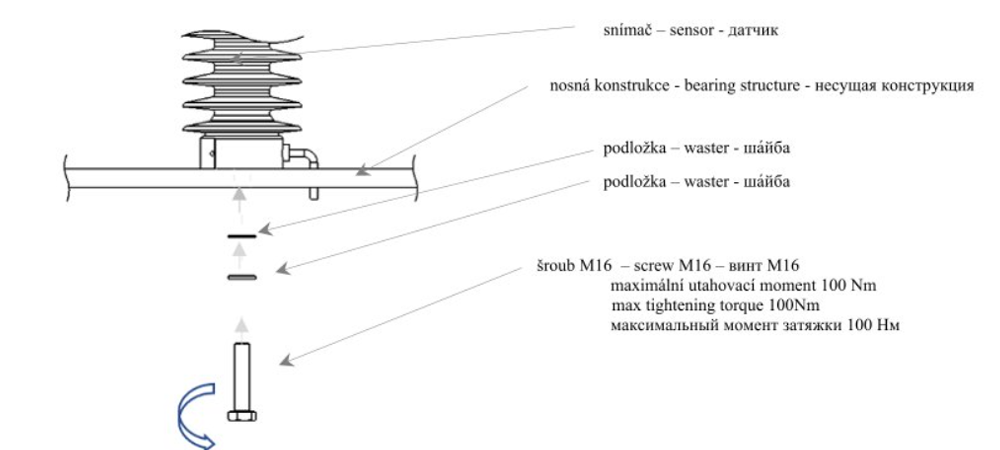
Pic. 2. 1-1 Basic principle of attaching the sensor to the support structure
The output cable of the sensor is fixed to the support structure and then to other elements of the installation site to prevent damage during both installation and subsequent operation.
The output cable of the sensor is designed for outdoor applications of sensors.
The minimum bending radius of the sensor cable for fixed installations is at least four times the diameter of the sensor’s output cable for fixed installations, and for flexible placement of the sensor cable, the minimum bending radius is ten times the diameter of the sensor’s output cable.
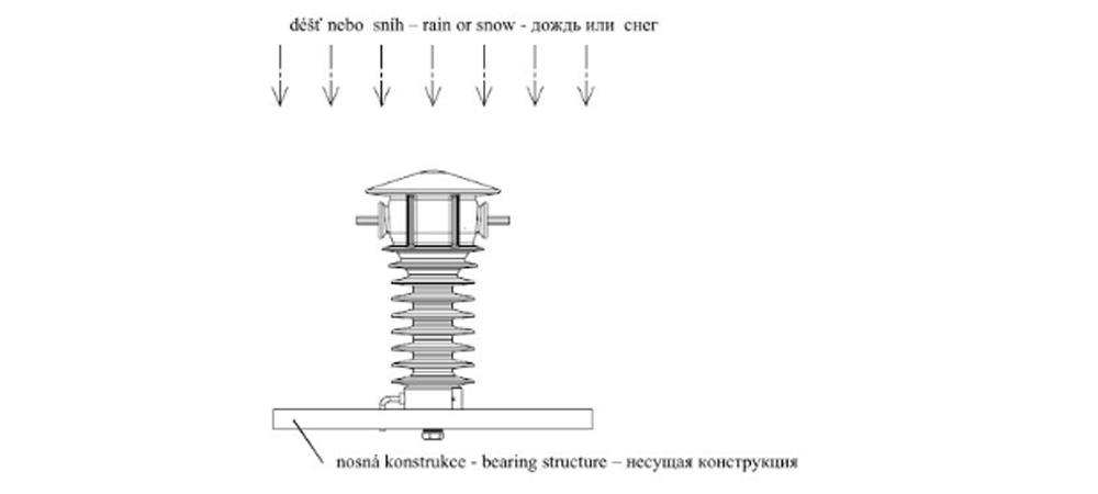
2.2. Installation position of sensors
The suitable installation position for sensors is such that under normal climatic conditions at the site of permanent sensor installation, there is no long-term or permanent accumulation or collection of precipitation on the body of the sensor. An example of a suitable installation position of the sensor with respect to external climatic influences is shown in the figure below. The image displays the position of the sensor and the support structure during proper installation. The figure represents an outdoor current sensor CSO 25. Other types of sensors CSO, VSO, and CVSO have an identical suitable position as shown with CSO 25. The support structure in all images is illustrative and may not correspond to the actual structure of the support structure of the sensor or sensors.
:
Pic. 2 2-1 Optimal Position of the Sensor
The least suitable permanent positions of outdoor sensors in adverse climatic conditions are shown in the images below. During heavy rainfall or persistent precipitation accumulation in these unfavorable positions, the manufacturer cannot guarantee all sensor parameters for the lifespan of the sensor.
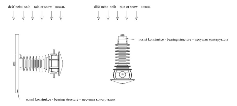
Obr. 2 2-2 Suboptimal position of the sensor
2.3. Connection of current sensors
The power circuit is connected to the primary galvanically nickel-plated terminals using an M12 screw with a maximum tightening torque of 70 Nm. The secondary side of the current sensor is connected using a flexible cable 3×1.5mm².
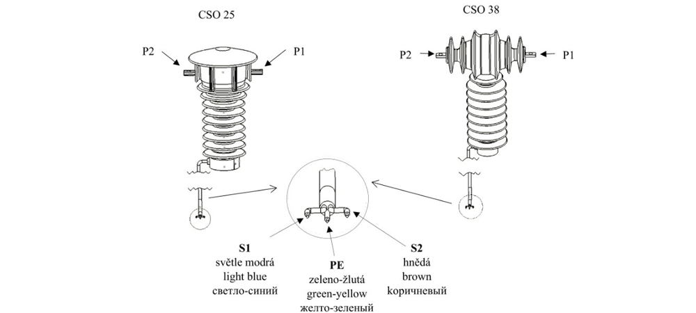
Pic. 2 3-1 Connection of current sensors
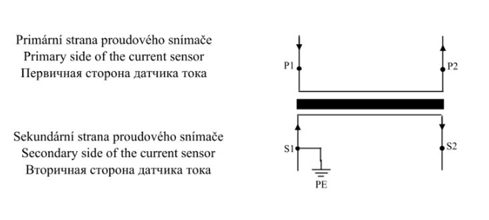
Pic. 2 3-2 Electrical connection of CSO type current sensor
CAUTION: WHEN OPERATING CURRENT SENSORS, IT IS NECESSARY TO PREVENT DISCONNECTION OF THE SECONDARY WINDING TERMINALS. IF THE SECONDARY OUTPUT OF THE CURRENT SENSOR IS NOT CONNECTED TO A MEASURING OR OTHER DEVICE, IT IS NECESSARY TO LINK THE TERMINALS OF THE CURRENT SENSOR AND CARRY OUT GROUNDING.
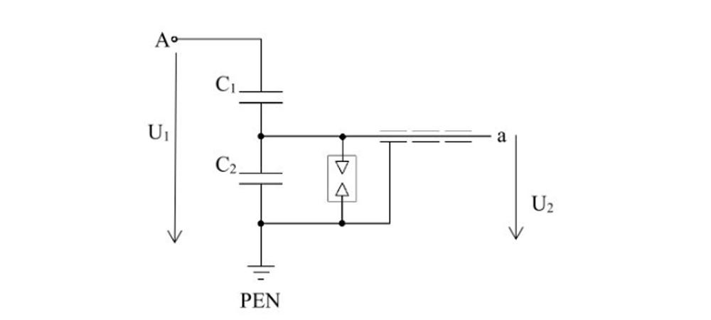
2. 4. Connection of VSO voltage sensors
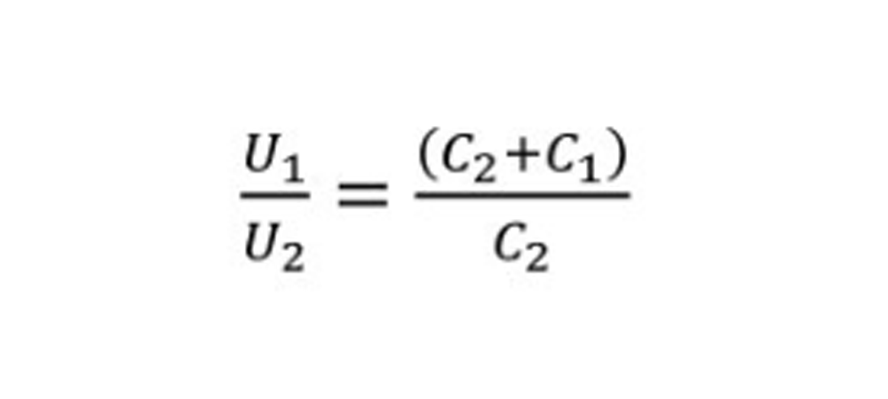
The power circuit is connected to the primary galvanically nickel-plated terminals using an M12 screw with a maximum tightening torque of 70 Nm. The secondary side of the voltage sensor is connected using a flexible shielded cable. VSO type sensors are a capacitive divider consisting of a high-voltage (C1) and a low-voltage (C2) capacitance. The high-voltage capacitance is formed by special electrodes embedded in epoxy casting material. The low-voltage capacitance is the inherent capacitance of the output cable.
:
Pic. 2 Electrical connection of VSO type voltage sensor
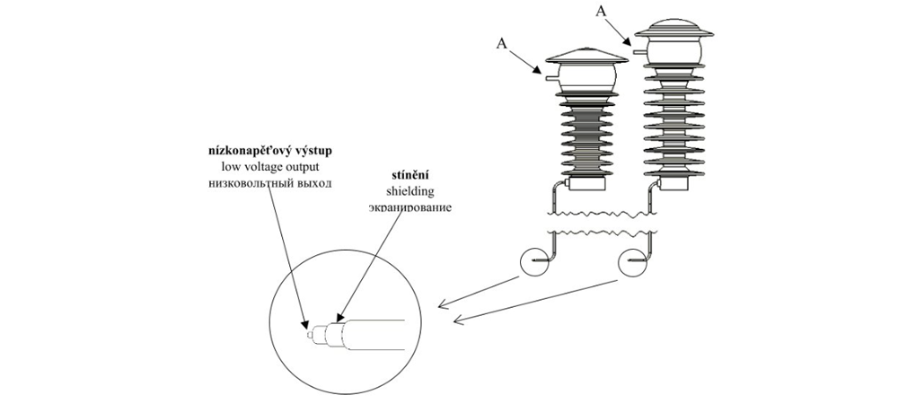
Pic. 2 4-1 Connection of voltage sensors
CAUTION! IF THE LOW-VOLTAGE OUTPUT OF THE CAPACITOR IS NOT ELECTRICALLY UTILIZED, IT MUST BE GROUNDED FOR SAFETY REASONS.
2.5. Connection of combined CVSO sensors
The power circuit is connected to the primary galvanically nickel-plated terminals of the sensor using an M12 screw with a maximum tightening torque of 70 Nm. The secondary side of both the voltage and current parts of the sensor is connected using flexible cables.
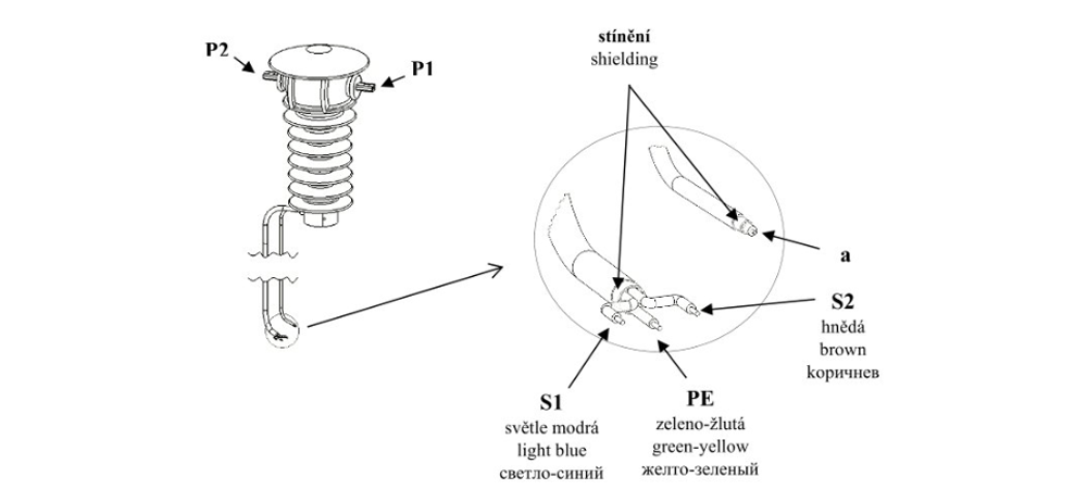
Pic. 2 5-1 Connection of combined sensors
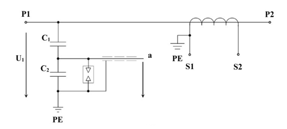
Pic. 2 5-2 Electrical connection of combined CVSO type sensor
CAUTION: WHEN OPERATING COMBINED SENSORS, IT IS NECESSARY TO PREVENT DISCONNECTION OF THE SECONDARY WINDING TERMINALS OF THE CURRENT PART OF THE SENSOR. IF THE SECONDARY OUTPUT OF THE CURRENT SENSOR IS NOT CONNECTED TO A MEASURING OR OTHER DEVICE, IT IS NECESSARY TO LINK THE TERMINALS OF THE CURRENT SENSOR AND CARRY OUT GROUNDING.
CAUTION! IF THE LOW-VOLTAGE OUTPUT OF THE CAPACITOR IS NOT ELECTRICALLY UTILIZED, IT MUST BE GROUNDED FOR SAFETY REASONS.
3. Commissioning of sensors – Initial revision
- check the completeness of sensor delivery
- verify the information on the sensor’s production label (check if the sensor’s insulation level corresponds to the insulation level of the installation site)
- assess the surface condition of the sensor
- verify the insulation condition of the current sensor using an insulation tester (for testing the low-voltage winding against the ground with an insulation tester at 1 kV and for testing the low-voltage winding of the current sensor against the high-voltage winding with an insulation tester up to 10 kV)
- check the polarity of the external circuit connections with respect to the sensor terminal markings and conformity with the installation diagram
- ensure proper tightening of primary terminals.
- check the connection of the low-voltage side of the sensor.
4. Operation of the sensor
If the sensor is used for a purpose other than that for which it was manufactured by the producer, or if it is used inappropriately, the producer bears no responsibility for such use or the damage caused by the sensor.
4.1. Operation of current sensors
When operating current sensors, disconnection of the secondary winding terminals must be prevented. If the secondary output of the current sensor is not connected to a measuring or other device, the terminals of the current sensor must be linked and grounded.
4.2. Operation of voltage sensors
If the low-voltage output of the capacitor is not electrically utilized, it must be grounded for safety reasons.
4.1. Operation of combined sensors
When operating combined sensors, disconnection of the secondary winding terminals of the current part of the sensor must be prevented. If the secondary output of the current part of the sensor is not connected to a measuring or other device, the terminals of the current sensor must be linked and grounded.
If the low-voltage output of the capacitor is not electrically utilized, it must be grounded for safety reasons.
5. Maintenance of Sensors
All maintenance of VSO, CSO, and CVSO sensors must be carried out with no voltage present in the electrical circuit to which the sensor is connected, and this circuit must be grounded throughout the maintenance period.
During voltage downtime, the following procedures are recommended:
- check the tightness of screws
- clean the surface of the sensor from dust or other types of contamination. Excessive dust or sand accumulation must first be removed with a brush from coarse impurities and then use a cloth impregnated with cleaner to clean the sensor from finer impurities. A contaminated transformer can be cleaned with technical alcohol, gasoline, or toluene. During cleaning, it is necessary to have safety work equipment prescribed by local legislation for working with cleaners in the defined environment and to prevent environmental pollution with the used cleaner
- check the sensor cable for any mechanical damage or disturbance
- minor damage to the outer surface of the sensor (traces of arc) can be removed with sandpaper, and then it is necessary to apply a thin layer of silicone paste (does not apply in case of cable damage)
- larger damage to the sensor should be consulted with the manufacturer
No other maintenance of the sensor is required for its operability.
6. Disposal of CSO, VSO, and CVSO type sensors
The disposal of CSO, VSO, and CVSO type sensors shall comply with national waste disposal regulations.
Cited Documents: ČSN EN 50110-1 ED. 3. Operation and work on electrical equipment – Part 1: General requirements. 2015. ČSN 34 3278 Operation and handling of instrument transformers. 1964.
The Instruction for the current transformes
The Instruction for the current transformes
The mounting position of the instrument transformers CTS, CTT and CTB is arbitrary. The transformers CTSO 38 are mounted in the vertical position.
The transformers are fixed by the means of four screws M10 (CTS 12) or M12 (CTS 25, CTS 25X, CTS 25X Sch,CTS 38, CTS 38X, CTS 38X Sch, CTSO 38, CTB 25, CTT 25) in the holes in the basic plate or in the profiles.The connection of the power circuit to the primary terminals is done by the means of the screws M12 (See picture No.1) with max. torque module 70Nm.We recommend use terminal ends corresponding to the used cross-section of the conductor (its maximum size is 10 mm2) for attaching to the secondary outlets.Metal functional parts of the transformer are coated against corrosion. The primary terminals are galvanized with nickel or silver-plated. The secondary terminals are galvanized with nickel. The basic plates are cold galvanized (transformers for the indoor settings) or hot galvanized (transformers for the outdoor settings).
We recommend clean transformers from dirt and draw close the connections in case of shut down.
Before starting-up it is necessary to earth the metal base of transformer (earthling “cube” with screw M8x15 with max.
torque module 10Nm see picture No. 1) and one secondary terminal of every outlet (See picture No. 2). The secondary
outlets, that were not used, are necessary to be short connected and earthed (See the examples in pictures No. 3-5).The
earthling of the secondary outlets is done by the means of screws M5x16 (max. torque 2.7 Nm) and jumpers (See picture No. 2) that arethe parts of the set of each supplied transformer.
:
Pic. 1 Mounting system of transformer CTS
Tightening torque max.
Primary terminal M12 70 Nm
Ground terminal 10 Nm
Secondary terminal M5 2.7 Nm
The construction of transformers allows the switching of the ranges on both the secondary and primary sides. The secondary switching is made by the means of switching of branches on the secondary coil. See the examples in picturesNo. 6-9. The primary switching has easy mounting, connecting two jumpers into the circuit by the means of screws M8 (both the screws and jumpers are the part of the set of the transformer). See the examples of interconnection inpictures No. 10-13.
Pic. 2 The way of connection of conductors to the secondary terminals, including of the earthing of one terminal for the transformers for the indoor and outdoor settings
The secondary terminal board is provided with the plastic cover with sealing cover and also, on the sides, with the threads Pg16 with screwed blinding and jumper for the drawing die of the secondary line-wires.The secondary terminal board of the transformers for the outdoor settings (type CTSO) is provided with the waterproofcover with sealing screw and waterproof bushing for the connection of the secondary line-wires.
The examples of circuit of the secondary terminal board of measuring current transformers, including special cases
There is the example of circuit of two-cored transformer with ratio 50//5/5 A in the picture No. 3. The terminals of the fi rst secondary winding (symbols 1S1 and 1S2) are connected to the external load and one terminal (in this case 1S1) is earthed. The second secondary winding (symbols 2S1 and 2S2) is not connected to the external load and so the terminals have to be interconnected in the short circuit and they have to be earthed. The wiring diagram is in picture No. 4. The mounting of the terminal board is in picture No. 5.
The example of mounting of the secondary terminal board of one-core transformer with the ratio 50-100//5 A and with the
switchingon the secondary side you can see in the following pictures. Picture No. 6 describes the connection for the ratio
50//5 A. Terminals S1 and S2 are brought out to the external load and one terminal (in this case S1) is earthed. The electric
scheme is in picture No. 7. The mounting for the ratio 100/5 you can see in picture No. 8. Terminals S1 and S3 are brought
out to the external load and terminal S1 has to stay earthed. Terminal S2 remains unassigned. Wiring diagram is in picture No. 9.
In the following case you can see the example of mounting of the primarily switchable transformer with the ratio 50-100//5 A. In picture No. 10 is shown the connection for the primary current of 100 A. Terminals P1, C1 and P2, C2 are interconnected by the means of the special connector and screws M8. Wiring diagram is in picture No. 11. The way of contacting for the primary current of 50 A is in picture No. 12. Terminals C1 and C2 are interconnected by the means of both connectors and screws M8. Scheme is in picture No. 13.
Note: The above-mentioned connections are recommended by the producer only in the caseswhere the expert designer does not determine other way.
Secondary terminal:
The Instruction for the voltage transformes
The mounting position of the instrument transformers VTS and VPT is arbitrary. The transformers VTO and VPT are only mounted in the vertical position. The transformers are fixed by the means of four screws M10 (VTS 12 and VTD 12) or M12 (VTS 25, VTS 38,VTD 25, VTO 38, and VTDOR 38) in the holes in the basic plate or in the profi les. The connection of high voltage to the primary side is recommended by the means of the terminal ends with 10 mm and screws M10 with max. torque module 20Nm. The example of mounting system of transformer is shown in picture No. 1 (VTS 12). For the contacting on thehigh voltage side of transformers with isolators we recommend to use the conductors of maximum diameter of 6 mm2 and terminal ends by the reason of springing of the dynamic forces within the system.
ATTENTION! The isolators must not be pre-stressed mechanically in the direction away from the body of transformer during the mounting process.
We recommend clean transformers from dirt and draw close the connections in case of shut down.
Before starting-up it is necessary to earth the metal base of transformer (earthling “cube” with screw M8x15 with max.torque module 10Nm see picture No.1).
Pic. 1 The example of mountingsystem of transformer (VTS 12)
The earthling of the secondary outlets is done by the means of screws M5x16 (max. torque 2.7 Nm) and jumpers (See picture No.2) that are
the parts of the set of each supplied transformer. The example of mounting is shown in picture No. 2.The construction of transformers allows the switching of the ranges on the secondary branches of transformer. The examples are shown on the following page. The secondary terminal board is provided with the plastic cover with sealing cover and also, on the sides, with the threads Pg16 with screwed blinding and jumper for the drawing die of the secondary conductors.The secondary terminal board of the transformers for the outdoor settings (types VTO and VPT) is provided with the waterproofcover with sealing screw and waterproof bushing for the connection of the secondary conductors.
ATTENTION! It is necessary to check after each starting-up whether the secondary winding is not earthed by one terminal on the terminal board and by the second terminal by the outlet in the low voltage part. Otherwise the instrument is connected in short way and after the starting-up of high voltage the destruction of the instrument occurs.
Pic 2. The way of connection of the secondary outlet and outlet of primary winding in earth of indoor and outdoor type of VTS and VTO
The examples of circuit of the secondary terminal board of measuring voltage transformers,including special cases
Single-pole instrument transformers of type VTS for the use of three-phased, inefficiently earthed systems are usually provided withtwo secondary windings. The first of these windings is used for the measurement or protection, the second for signaling of earthconnection. They are linked up in three phases – the primary and secondary windings are star-connected, auxiliary winding in open triangle (See wiring diagram in picture No.3).
Terminal “N” of the primary winding, one terminal of the secondary winding and one of the end terminals of the open triangle have to be earthed during the operation. (ATTENTION! In case of earthling of the open triangle on two terminals there is the danger of instrument destruction.) The example of circuit of terminal board is shown in picture No. 4.
Pic. 3 Wiring diagram of triple of single-poled transformers
In the following case you can see the example of switchable single-poled transformer with the ratio 6600-11000/√3//100/√3 V. The switching is possible due to branch on the secondary winding. Picture No. 5 shows the scheme for the ratio /√3//100/√3 V. The measuring outlet is between the terminals a1 – n, terminal a2 remains unassigned. The mounting of terminal board is shown in picture No. 6. The scheme for the ratio 11000/√3//100/√3 V is shown in picture No. 7. The measuring outlet is here between terminals a2 – n, terminal a1 remains unassigned. The mounting of terminal board is shown in picture No. 8.
Double-poled instrument transformers VTD and VPT have all parts of primary winding, including terminals, isolated from earth. The isolation is dimensioned on the level of testing voltages according to the corresponding nominal voltage.One of the secondary terminals must be earthed during the operation (it is not the case of the so called “V- connection”).
Wiring diagram of transformer is shown in picture No. 9. The connection of terminal board for indoor setting is shown in picture No. 10 and for outdoor setting in picture No. 11.
Note: The above-mentioned connections are recommended by the producer only in the cases where theexpert designer does not determine other way.
Secondary terminal:
The Instruction for the voltage transforme VPT 100
Connection
The connection of the regulating source and transformer VPT 100 is done according to the following diagram:
Pic. 1 VPT 100 scheme
We insert interconnection in the side-wall of regulator REG 100 or we connect the end switcher of the inlet door of the area of high voltage.
We interconnect the cable leading from transformer and the regulator (non-typical socket of 380V). We make earthling of transformer (there is earthling connector M8 on the skeleton of instrument). We connect the outlet of high voltage with the tested object. We connect the ending of the lead-in wire in the socket of AC 220V.
Description of handling
We switch on the supply from the source of 220V with the switch “Main switch”. We turn the button of regulator at the value of “0”. We switch on the green button “START”. The signal red bulb will switch on. The red bulb informs the personnel about the state under the voltage. We turn continuously the button of regulator to the right and we increase the voltage on the output of transformer until we reach the required level. During this process we can see on the panels of instrumentscurrent demand and the level of exciting voltage. When we overstep the current 14A (it is 3kVA) the protection A15 starts and disconnects transformer from the excitement within the moment. (The red bulb will switch off.) For the restarting of the function it is necessary to turn the regulator button to the value of “0” and to push the button “START”. The red button “STOP” is for the disconnection of the source of excitement. After fi nishing the operation of the instrument we recommend to switch “Main switch” off, to turn the button of regulator to the value of “0” a to earth the high voltage outlet of transformer
Safety of work
The instrument can be operated only by the person that fulfi lls the rules of regulation 50/1978. At the same time this person must follow the instructions for the work in the testing laboratories of high voltage.
:
Pic. 2 Scheme of transformer
The Instruction for the voltage transformes VPPT 38.2
The appliance transformer VPPT 38.2 shall be installed in the position with its epoxide body above the metal foundation sections.
The transformers are fixed with four screws M12 by the holes in the foundational sections. We recommend connecting of HV on the primary side by means of cable lugs of a diameter of 10 mm and screws M10 of a max. tightening torque of 20 Nm. In case of a shut-down we recommend cleaning of the transformers from rough dirt and tighten the joints.
Before putting the transformer into operation it is necessary to earth the metal sections of the transformer (earth screw M8x15 with a max. tightening torque of 10 Nm).
Earthing of secondary outputs is done by means of screws M5x10 and jumpers, which are included in the delivery of every transformer. Connection to the secondary leads is provided by means of cable lugs (for the 10mm2 wire, they are included in the accessories). An example of installation is in Fig.1.
The secondary terminal block is fitted with a water-resistant IP 65 cover with a sealing screw and water-resistant bushing Pg21 for connection of secondary conductors.
All components of the primary winding of appliance transformers VPPT, including terminals, are insulated from the earth. Insulation is dimensioned for the level of test voltages according to the corresponding rated voltage.
During the operation, one of the secondary terminals must be earthed (this does not apply to so-called V-connection).
Note: The described connections are recommended by the manufacturer to be used only where the professional project engineer does not specify otherwise.
Smart Load to AFR 30 Reduce Ferroresonance
The AFR 31 Smart Load is an instrument designed to protect metering voltage transformers against adverse effects of ferroresonance in high voltage power distribution systems with ungrounded or indirectly grounded neutral wire. Ferroresonance comes up between transformer inductance and conductors’ or switching elements’ capacitance. Connecting, disconnecting, ground connection or other transitional effects may be the trigger events. Ferroresonance oscillations cause significant overvoltage and current surges as a result of transformer magnetic circuit saturation. This most often leads to metering transformer destruction.
AFR 1 Smart Load acts as metering voltage transformer protection against such effects. Unlike other methods, it is targetedly enabled only when ferroresonance occurs, being passive in common operation or with nonsymmetrical loads.
Magnitude of trigger voltage can be adjusted to 20, 25 or 30 volts. For selectivity with ground connection protection devices an activation time delay circuit (4 seconds as default) is used. This is suitable at installations where a voltage transformer is used not only for measuring but as power supply for protection devices too (ground connection detection, automatic reconnection circuits etc.).
The AFR 31 is designed to be installed on a 35-millimeter DIN strip (DIN EN 50 022).
The AFR 31 works in conjunction with a metering voltage transformer while open delta is connected to auxiliary windings (terminals da, dn). One of pole must be grounded. Before connection. The open delta configured auxiliary windings may be, together with the AFR 31 Smart Load, used for ground connection protection relay, which is to be connected in parallel to AFR 31 using the protection relay manufacturer’s recommendations. AFR 31 parallel connection does not affect protection relay operation.
Nominal voltage 100/3, 110/3, 120/3 VAC
Activation voltage no jumper 20 VAC
3+4 jumper 25 VAC (default)
1+3 jumper 30 VAC
Activation delay 4.0 sec (other value in range 0.5 ÷ 10sec on request)
Protection degree IP20
Overvoltage class II
Climate class 5 / 50 / 40
Operating temperature -20°C ÷ 40°C
Storage temperature -20°C ÷ 70°C
Maximum humidity 95 % non-condensing
Dimensions 69 x 86 x 58 mm
Mass 0,05 kg
Material of cover polycarbonate
Instalation 35 mm DIN bar mount (DIN EN 50 022)
Connection screw terminals, 0.5 ÷ 2.5 mm2 wire cross section
Wireup
Desired activation voltage must be set before installation. Release snap-in latches with an appropriate size screwdriver and remove the instrument cover.
You can set on of three levels according technical parameters table. Default activation voltage level is preset to 25 V. Higher level is suitable for high voltage grids with higher unbalance of parasitic capacities. After setting, and snap in the rear panel back (keep attention to the correct LED light pipe position).
The AFR 31 is designed to be installed on a 35-millimeter DIN strip (DIN EN 50 022) and for indoor use only.
Natural air circulation should be provided inside the distribution board cabinet, and in the instrument’s neighborhood, especially underneath the instrument, no other instrumentation that is source of heat should be installed. The instrument must be installed in indicated position with its terminals oriented down, usually in the measuring and protection control panels.
The AFR 31 works in conjunction with a metering voltage transformer while open delta is connected to auxiliary windings (terminals da, dn) as shown in the wiring diagram below. 2.5 square millimeter copper wire is recommended for the circuit. One of pole must be grounded. Before connection, check the grounding both at the transformer and the load side to avoid unwanted duplicity; otherwise measuring voltage transformers can be short-circuited and destroyed.
The open delta configured auxiliary windings may be, together with the AFR 31 Smart Load, used for ground connection protection relay, which is to be connected in parallel to AFR 31 using the protection relay manufacturer’s recommendations. AFR 31 parallel connection does not affect protection relay operation.
Smart Load wireup diagram in metering voltage transformer auxiliary winding open delta configuration
Assembly of insulator with fuse – VTO 38P
- We put the fuse into the epoxy insulator and insert it into the contact.
- The fuse has to be centred to the middle of the cavity.
- Then we put the ring seals on the thread part of transformer body.
- We check the thread and possibly remove the dirt.
- We screw the insulator with the fuse very carefully and tighten it by hand.
When installing the thread, we take care not to screw beyond the thread. Tighten the thread within the elasticity limits of the seal. The thread must not be stripped!
The Instructions for the secondary LV fuses
Fusing on the secondary side of the transformer is used in the event of a short circuit in the secondary winding. A short circuit in the secondary winding can occur, for example, due to improper connection of the secondary winding or cable interruption. In response to this, a transformer with a low-voltage (LV) fuse (Fig. 1) incorporated into the secondary winding (Fig. 2) was designed.
:
Pic. 2A Terminal block VPT 25 with secondary fusing
:
Pic. 2B Scheme of diagram
Pic 1. Low voltage instrument fuse
Assembly procedure
The image shows a secondary terminal block with the FPG2 fuse casing.
The fuse is removed using a screwdriver. The screwdriver must have a head size of no more than 1×5 mm. Insert the screwdriver into the slot in the fuse casing and turn it to the left. This releases the fuse cap with the fuse inside, which can then be easily removed by hand. After that, the LV instrument fuse within the fuse cap is easily replaced by hand.
Following the manual replacement of the LV instrument fuse in the fuse cap, the cap is easily reinserted into the fuse casing by hand. A screwdriver is then inserted into the slot. The screwdriver must have a head size of no more than 1×5 mm. The fuse is secured with the screwdriver by gently pressing and turning it to the right.
Other technical parameters can be consulted with the manufacturer.
- View into the terminal block
- Removing the fuse
- Installing the fuse
Non-standard effects in networks and their impact on Voltage Instrument
General Principles of Prevention and Protection
Ferroresonance
This effect has already been described in many publications. In principle it refers to an exchange of electrical energy between the capacitance and inductance of a transformer. In the course of the ferroresonance effect, the magnetic core of the transformer becomes oversaturated, followed with overcurrents causing destruction. The prevention consists in:
Loading the voltage transformer always with a burden, only a small one, consisting from an electronic W-meter or protection relay. In this a way, the startup of resonance effects will be curtailed.
Damping of the already arisen ferroresonance phenomenon can be done using e.g. a special resistance (KPB Intra sells a resistance of 68 Ohm/2000 W for this purpose), or the AFR 31 device, which is to be embedded in the auxiliary windings connected in opened delta.
In special cases, in particular when this phenomenon has arisen repeatedly, it is necessary to notify the manufacturer of the transformers, i.e. the company KPB Intra. Based on experiences gathered with the so called undersaturation of the magnetic core the principle mentioned above can be augmented and the occurrence of ferroresonance be prevented or its effects limited.
Atmospheric overvoltages
External protection consists in the use of surge arresters.
Switching overvoltages
Structural protection consists in the reinforcement of insulation of the input turns of the MV transformer winding.
External protection consists in the usage of surge arresters.
Short-circuits in the secondary winding
When connecting the windings it is necessary to avoid a double earthing of the same, e.g. by connecting one terminal of the secondary winding to the earth in the secondary terminal block of the transformer, and the other terminal to e.g. an earthed energy meter.
Auxiliary windings connected in delta may be earthed at one point, only.
Short-circuit can be prevented also by using adequate circuit breakers or fuses, connected to the secondary terminal block (the VPT 25 does include fuses incorporated in the secondary terminal block).
General protection
Generally, voltage transformers are protected from explosion by fuses mounted on the MV side. The manufacturer recommends their usage and the fuses are delivered by him with appropriate parameters. It is important to realize that the fuse above is not capable of saving the transformer, but it may reduce the effects of the transformer explosion on the environment.
The above recommendations refer in particular to projects installed at exposed points of the network, such as mines, railways, transition points from HV onto MV, and recently also in the photovoltaics and biogas stations.
The Instruction for the high voltage detection with dry insulation up to 38 kV manufactured by KPB INTRA s. r. o.
This document applies to:
- voltage sensors: VSO xxx
- current sensors: CSO xxx
- combined sensors: CVSO xxx
Note: ‘xxx’ in the type designations represent individual types and subtypes.
This document serves as a recommendation from the manufacturer of transformer sensors. It is always necessary to comply with local legislative conditions and regulations, including internal company rules and procedures during installation, commissioning, operation, maintenance, and disposal, to prevent harm to health, economic damages, and environmental hazards.
1. General Requirements
VSO and CSO sensors are electrical devices that should only be operated and checked by knowledgeable individuals with higher qualifications meeting the requirements of the ČSN EN 50110 – 1 standard and subsequent related and cited technical standards, local laws, decrees, internal company standards and guidelines, along with relevant safety rules.
If national legislation does not specify requirements for the qualifications of individuals, the following safety criteria must be met to assess suitability:
- electrical engineering education
- experience in working with electrical equipment
- knowledge of the equipment to be worked on and practical experience with such work
- awareness of potential hazards that may occur during work
- ability to assess under all circumstances whether it is safe to continue working. Before starting any work activity, an analysis of its complexity should be conducted to select a suitable, knowledgeable, educated, or acquainted individual for its execution.
All activities related to sensors must not be performed by personnel under the influence of alcohol or other addictive substances. The safety of individuals involved in work activities and those who are or may be affected by these activities must comply with national legislation.
Before starting any activity on electrical equipment, an assessment of the electrical risk must be conducted and based on this, it should be determined how these activities will be carried out and what safety measures must be taken to ensure safety.
For all activities related to the installation, testing, operation, maintenance, and disassembly of sensors, all tools, equipment, and instruments used in these activities must meet the requirements of the relevant international, European, or national standards, if they exist. The mentioned connections are recommended by the manufacturer only where the professional designer does not specify otherwise.
2. Installation and Assembly
Before the actual installation of the sensor, it is necessary to:
- assess the surface condition of the sensor
- check the information on the sensor’s production label (verify if the sensor’s insulation level corresponds to the insulation level of the installation site)
- inspect the sensor cable for any damage
2.1. Mechanical attachment of sensors
CSO, VSO, and CVSO type sensors are mechanically attached to the support structure using an M16 screw. The length of the screw depends on the support structure of the sensor. The screw is threaded into a casting nut that is embedded in the bottom part of the sensor. The screw should be tightened with a torque wrench to a maximum tightening torque of 100 Nm.
Pic. 2. 1-1 Basic principle of attaching the sensor to the support structure
The output cable of the sensor is fixed to the support structure and then to other elements of the installation site to prevent damage during both installation and subsequent operation.
The output cable of the sensor is designed for outdoor applications of sensors.
The minimum bending radius of the sensor cable for fixed installations is at least four times the diameter of the sensor’s output cable for fixed installations, and for flexible placement of the sensor cable, the minimum bending radius is ten times the diameter of the sensor’s output cable.
2.2. Installation position of sensors
The suitable installation position for sensors is such that under normal climatic conditions at the site of permanent sensor installation, there is no long-term or permanent accumulation or collection of precipitation on the body of the sensor. An example of a suitable installation position of the sensor with respect to external climatic influences is shown in the figure below. The image displays the position of the sensor and the support structure during proper installation. The figure represents an outdoor current sensor CSO 25. Other types of sensors CSO, VSO, and CVSO have an identical suitable position as shown with CSO 25. The support structure in all images is illustrative and may not correspond to the actual structure of the support structure of the sensor or sensors.
:
Pic. 2 2-1 Optimal Position of the Sensor
The least suitable permanent positions of outdoor sensors in adverse climatic conditions are shown in the images below. During heavy rainfall or persistent precipitation accumulation in these unfavorable positions, the manufacturer cannot guarantee all sensor parameters for the lifespan of the sensor.
Obr. 2 2-2 Suboptimal position of the sensor
2.3. Connection of current sensors
The power circuit is connected to the primary galvanically nickel-plated terminals using an M12 screw with a maximum tightening torque of 70 Nm. The secondary side of the current sensor is connected using a flexible cable 3×1.5mm².
Pic. 2 3-1 Connection of current sensors
Pic. 2 3-2 Electrical connection of CSO type current sensor
CAUTION: WHEN OPERATING CURRENT SENSORS, IT IS NECESSARY TO PREVENT DISCONNECTION OF THE SECONDARY WINDING TERMINALS. IF THE SECONDARY OUTPUT OF THE CURRENT SENSOR IS NOT CONNECTED TO A MEASURING OR OTHER DEVICE, IT IS NECESSARY TO LINK THE TERMINALS OF THE CURRENT SENSOR AND CARRY OUT GROUNDING.
2. 4. Connection of VSO voltage sensors
The power circuit is connected to the primary galvanically nickel-plated terminals using an M12 screw with a maximum tightening torque of 70 Nm. The secondary side of the voltage sensor is connected using a flexible shielded cable. VSO type sensors are a capacitive divider consisting of a high-voltage (C1) and a low-voltage (C2) capacitance. The high-voltage capacitance is formed by special electrodes embedded in epoxy casting material. The low-voltage capacitance is the inherent capacitance of the output cable.
:
Pic. 2 Electrical connection of VSO type voltage sensor
Pic. 2 4-1 Connection of voltage sensors
CAUTION! IF THE LOW-VOLTAGE OUTPUT OF THE CAPACITOR IS NOT ELECTRICALLY UTILIZED, IT MUST BE GROUNDED FOR SAFETY REASONS.
2.5. Connection of combined CVSO sensors
The power circuit is connected to the primary galvanically nickel-plated terminals of the sensor using an M12 screw with a maximum tightening torque of 70 Nm. The secondary side of both the voltage and current parts of the sensor is connected using flexible cables.
Pic. 2 5-1 Connection of combined sensors
Pic. 2 5-2 Electrical connection of combined CVSO type sensor
CAUTION: WHEN OPERATING COMBINED SENSORS, IT IS NECESSARY TO PREVENT DISCONNECTION OF THE SECONDARY WINDING TERMINALS OF THE CURRENT PART OF THE SENSOR. IF THE SECONDARY OUTPUT OF THE CURRENT SENSOR IS NOT CONNECTED TO A MEASURING OR OTHER DEVICE, IT IS NECESSARY TO LINK THE TERMINALS OF THE CURRENT SENSOR AND CARRY OUT GROUNDING.
CAUTION! IF THE LOW-VOLTAGE OUTPUT OF THE CAPACITOR IS NOT ELECTRICALLY UTILIZED, IT MUST BE GROUNDED FOR SAFETY REASONS.
3. Commissioning of sensors – Initial revision
- check the completeness of sensor delivery
- verify the information on the sensor’s production label (check if the sensor’s insulation level corresponds to the insulation level of the installation site)
- assess the surface condition of the sensor
- verify the insulation condition of the current sensor using an insulation tester (for testing the low-voltage winding against the ground with an insulation tester at 1 kV and for testing the low-voltage winding of the current sensor against the high-voltage winding with an insulation tester up to 10 kV)
- check the polarity of the external circuit connections with respect to the sensor terminal markings and conformity with the installation diagram
- ensure proper tightening of primary terminals.
- check the connection of the low-voltage side of the sensor.
4. Operation of the sensor
If the sensor is used for a purpose other than that for which it was manufactured by the producer, or if it is used inappropriately, the producer bears no responsibility for such use or the damage caused by the sensor.
4.1. Operation of current sensors
When operating current sensors, disconnection of the secondary winding terminals must be prevented. If the secondary output of the current sensor is not connected to a measuring or other device, the terminals of the current sensor must be linked and grounded.
4.2. Operation of voltage sensors
If the low-voltage output of the capacitor is not electrically utilized, it must be grounded for safety reasons.
4.1. Operation of combined sensors
When operating combined sensors, disconnection of the secondary winding terminals of the current part of the sensor must be prevented. If the secondary output of the current part of the sensor is not connected to a measuring or other device, the terminals of the current sensor must be linked and grounded.
If the low-voltage output of the capacitor is not electrically utilized, it must be grounded for safety reasons.
5. Maintenance of Sensors
All maintenance of VSO, CSO, and CVSO sensors must be carried out with no voltage present in the electrical circuit to which the sensor is connected, and this circuit must be grounded throughout the maintenance period.
During voltage downtime, the following procedures are recommended:
- check the tightness of screws
- clean the surface of the sensor from dust or other types of contamination. Excessive dust or sand accumulation must first be removed with a brush from coarse impurities and then use a cloth impregnated with cleaner to clean the sensor from finer impurities. A contaminated transformer can be cleaned with technical alcohol, gasoline, or toluene. During cleaning, it is necessary to have safety work equipment prescribed by local legislation for working with cleaners in the defined environment and to prevent environmental pollution with the used cleaner
- check the sensor cable for any mechanical damage or disturbance
- minor damage to the outer surface of the sensor (traces of arc) can be removed with sandpaper, and then it is necessary to apply a thin layer of silicone paste (does not apply in case of cable damage)
- larger damage to the sensor should be consulted with the manufacturer
No other maintenance of the sensor is required for its operability.
6. Disposal of CSO, VSO, and CVSO type sensors
The disposal of CSO, VSO, and CVSO type sensors shall comply with national waste disposal regulations.
Cited Documents: ČSN EN 50110-1 ED. 3. Operation and work on electrical equipment – Part 1: General requirements. 2015. ČSN 34 3278 Operation and handling of instrument transformers. 1964.
Smart Load AFR 30
Smart Load AFR 30
The AFR 30 Smart Load is an instrument designed to protect metering voltage transformers against adverse effects of ferroresonance in high voltage power distribution systems with ungrounded or indirectly grounded neutral wire. Unlike other methods, it is targetedly enabled only when ferroresonance occurs, being passive in common operation or with nonsymmetrical loads or single-phase ground connection, which means it does not load the metering system.
Ferroresonance comes up between transformer inductance and conductor or switching element capacitance. Connecting, disconnecting, ground connection or other transitional effects may be the trigger events. Ferroresonance oscillations cause significant overvoltage and current surges as a result in very high transformer magnetic circuit saturation. This most often leads to metering transformer destruction.
AFR30 Smart Load acts as metering voltage transformer protection against such effects. Unlike other methods, it is targetedly enabled only when ferroresonance occurs, being passive in common operatin on with nonsymmetrical loads or single-phase ground connection, which means it does not load the mettering system.
Nominal voltage 100 – 200 VAC
Insensitivity window 0 – 20 VAC
Coverage IP20
Overvoltage class II
Climate class 5 / 50 / 40
Operating temperature -20°C až 40°C
Storage temperature -20°C až 70°C
Maximum humidity 95 % non-condensing
Dimensions 69 x 86 x 58 mm
Mass 0,05 kg
Material of cover polycarbonate
Instalation on 35 mm DINstrip in compliance with DIN EN 50 022
Connection terminal bar, wire cross section 0.5 to 2.5 sq mm
Wireup
AFR30 works in conjuction with a mettering voltage transformer while open delta is connected to auxiliary windings (terminals da, dn). Metering winding wiring is not changed. The open delta configured auxiliary windings may be, together with AFR30 Smart Load, used for ground connection protection relay, which is to be connected parallel to AFR30 using the protection relay manufacturer’s recommendations. AFR30 parallel connection does not affect protection relay operation.
AFR 30 Smart Load is usually installed in the measuring and protection control panels. The instrument is designed to be installed on a 35 mm DIN strip. 2.5 square millimeter copper wire is recommended for the circuit.
Smart Load wireup diagram in metering voltage transformer auxiliary winding open delta configuration
A, N: Metering transformer high voltage terminals
a, n: Secondary metering winding
da, dn: Other secondarywinding terminals
AFR30: Smart Load
symbol PE PE
Connection of instrumental voltage and current transformers
Connection of instrumental voltage and current transformers
KPB Intra s.r.o.
Ing. Josef Stejskal
Experience with connection of instrument transformers indicates that not every installation company is completely clear on how to connect the converter in practice. Examples of correct connection, potential errors and their prevention are described below.
Instrument voltage transformers
It applies generally that a voltage transformer may not be operated till a short circuit and, if it takes place, an explosion follows very shortly after it. The explosion results in consequent damage of adjacent equipment.
Connection of three earthed transformers with one measuring and one auxiliary winding should be done in accordance with the diagram in Fig. 1. Voltmeters are connected to the measuring windings (100/√3 V). One of the terminals is always earthed (“n” terminal here).
:
Pic. 1
:
Pic. 2
The auxiliary winding (100/3 V) is connected in a so-called “open triangle”. Unlike the preceding case, earthing is done at only one point here. For an example of connection in practice please see Fig. 2.
One of the errors of installation companies is earthing of an open triangle similarly as in the case of the measuring windings, i.e. one of the terminals of the secondary circuit is connected to the earth. However, earthing of not only the “da” terminal but also the “dn” terminal takes place here with respect to the character of connection and the transformers are operated until a short circuit occurs. An explosion occurs consequently.
Insufficient checking is another error that appears in practice. There are cases where one installation company performs connection of the measuring winding of transformers in accordance with Fig. 1, i.e. it applies earthing of the “n” terminal. This company only performs installation of transformers. Another company will connect voltmeters and use their earthing terminal for earthing. However, this terminal has already been connected with the “a” terminal of the transformer through the supply line. General connection is not verified by anybody. The instruments then operate until a short circuit occurs and an explosion is a matter of several seconds.
Instrument current transformers
A certain advantage of installation of current transformers is the fact that explosions do not occur in the case of an error in connection; however, damage of the instrument or risk for the operator may also occur here.
It applies generally that the secondary outlets are either connected to the burden or interconnected to the short circuit and one of the outlets is earthed. This principle is apparent from Fig. 3 and Fig. 5. Several errors are made in practice. Non-earthing one of secondary terminals may be one of them. Capacitive coupling is created then and the secondary circuit emits sparks on the frame. Conductive paths are created in the case of longer duration.
:
Pic. 3
:
Pic. 4
Ambiguities with the switch-over type of transformer can be another source of errors. A correct example of connection is illustrated in Fig. 4. It is apparent here that one terminal always remains free. An error occurs if this terminal is earthed. The transformer stops measuring then.
The above described errors may be prevented using several methods. Primarily, installation must be carried out by competent persons with practise in the given field. If they have not required experience, they must study installation instructions attached to each instrument or catalogue documentation (see “Operation and installation instructions”). It is also necessary to perform inspection of a general circuit, i.e. not only operations performed by each individual company, but connection as a unit and its compliance with the design. After all, disconnection of wires and then measuring with an ohmmeter is sufficient for verification of earthing of terminals and burdens.
Practical experience with installation of converters, potential errors and methods of their rectification are described above.
We hope to contribute to understanding of issues and prevention of consequent potential damages by giving the explanation above.
:
Pic. 5
Protection of voltage and transformers against ferroresonance
KPB Intra s.r.o.
Ing. Josef Stejskal
The phenomenon of „ferroresonnance “ can occur in single –pole voltage transformers in HV inadequately earthed cable
networks. The impedance of transformer and the earthing capacity of the cable create a potentially oscillating RLC circuit.
When an overvoltage come by the case of earth connection or some switching, the phenomenon of ferroresonnance can
appear. The consequences are overheating of magnetic core and coil, damage of insulation and burst.
To prevent HV equipment we recommend to use connection of dump resistor in open delta of additional secondary windings
(see picture 12 below). Mounting dimensions are in the picture 13. The value of resistance is 68 Ohm/ 200W (type
of TR305 producer is „ Tesla Blatná“).
Resistor is available to order in our firm and we can deliver it single or with other
transformers. We recommed to use it in new installations as prevention.
We hope to contribute to understanding of issues and prevention of consequent potential damages by giving the explanation above.
:
Dumping rezistor 68 Ohm /200W
:
TR 305 68R/J, H5 and TR 305 68R/J, V2
Ferroresonance is still relevant
KPB Intra s.r.o.
Ing. Josef Stejskal
The phenomenon called “ferroresonance” has already been described in many publications. For the uninitiated, it may be briefly stated that this involves a phenomenon found in electrical networks, where resonance occurs between an induction transformer and a capacity main. We shall leave aside a more detailed explanation for now (for those interested, the necessary information may be obtained on the Internet). It must be said, however, that resonances are harmful to high voltage equipment and often lead to permanent damage. As manufacturers of metering transformers, we therefore feel obligated to draw attention to the relevance of the given problem.
Experience from recent years has been referenced in frequent responses to customers at which interruption of a current metering transformer has occurred in connection with the replacement of older electromechanical electrometers with new electronic ones. In principle, such an exchange should not cause any difficulties, but when we think more deeply about this, unwittingly, greater susceptibility to ferroresonance may occur. The essence is that the new electronic electrometers have an internal load substantially lower than the original electromechanical system. This leads to so-called “stress reduction” of the transformer and subsequently to a decrease in the dampening effect of possible resonances.
To this actuality, often this leads to a frequent psychological error by designers. It has long been the experience of the human subconscious where professional dimensioning is unknown. In the field of current metering transformers (CMT), this occasionally leads to a requirement for higher outputs in relation to the degree of precision without any justification. Here, however, it is necessary to note structural links. Dimensioning of a transformer for higher output may be none other than increasing the dimensions, both the primary as well as the secondary conductors and by decreasing both active resistances. The result is evident in the decrease in the dampening effect of ferroresonance.
Another reason for the susceptibility to ferroresonance is the lack of communication from the side of the customer, i.e. designer, users… The origin of this situation is again in human psychology. Because, for example, if this leads to damage to the CMT even after several replacements, according to business logic, the transformer is always to blame. According to lay reasoning – how could it be otherwise, particularly if the equipment is still within the warranty period? According to experience with business rules, most dealers therefore select the method in which “it is necessary to submit a claim without describing the relationships of the equipment and with the conviction that if the manufacturer refuses the claim we will turn elsewhere”. But the question is put forth as to whether such a procedure actually resolves the problem. The opinion of our manufacturers of this equipment is that this isn’t entirely certain. Many customers, after numerous interruptions of the CMT under specific circumstances, admit that this or that installation point is actually problematic, that there were already problems with overvoltage and the breakdown occurred in other components (absence of safeguards). I write about this primarily to emphasize that technical problems must always be resolved by only technical means. For a successful resolution, a manufacturer needs to be informed about all the circumstances, on principle in advance.
If we notice that problems have already occurred somewhere, which are marked by the occurrence of ferroresonance, we recommend several solutions:
1. One is the universally known connection of dampening resistance in the perimeter of an open triangle helped by coiling, see details at www.kpbintra.cz.
2. In other cases (particularly at railways), we propose transformers with a lower saturation of the magnetic perimeter. Such instruments are larger and more expensive, but their resistance to resonance compensates for the costs related to removal of defects from previous designs.
3. In other cases, particularly in open pit mines, reinforcing the insulation of the primary coiling is beneficial after adapting the other parameters of the machine.
From the aforementioned, it is apparent that the problem of ferroresonance is still relevant in electrical networks.
Experience shows that designed technical solutions have demonstrated their reliability over the years. The solution, however, has always been reached after mutual communication with the manufacturer.
Fuses for high voltage measuring transformers
KPB Intra s.r.o.
Ing. Josef Stejskal
Use of fuses for voltage transformers is a long-term custom supported by rich experience. A fuse is a protective element that ensures transformer disconnection from network circuits by switching off the currents exceeding the rated value. Switching off a current usually results from a defect of the insulation system of the transformer; however, transient phenomena and ferro-resonance currents also cannot be excluded in many cases. The fuse usually switches off upon bursting of the transformer and development of an electric arc. It means that the function of fuses consists in protection of the surroundings against destructive effects.
High voltage current protections are the new protective component. In KPB Intra they are produced in two-type dimensions into electric system up to 22kV and also for 35kV (picture 5). Rated current protections are 32,50 and 80mA. High voltage will be switched off and disconnected at their exceed. Current protections position predetermines their higher sensitivity for overcurrents than at current fuses. Their contribution is faster frequent disconnection often before its explosion.
:
Pic. 1
:
Pic. 2
The company offers application of fuses in transformers in several modifications, e.g. Fig. 1 shows a fuse in the horizontal position with an outlet in its axis. A fuse in the horizontal position with an outlet in the vertical axis of the transformer is another variant, see Fig. 2. The third method is represented by a vertical fuse in the axis of instrument high voltage with the outlet on a cable, see Fig. 3. Fuse carriers are located in epoxy casing. Connection to the transformer high voltage terminal is made by means of a screw; lug type thread is illustrated in Fig. 2.
:
Pic. 4
:
Pic. 5
Pic. 3
VTS38 transformers for 35 kV networks illustrated in Fig. 4 can be fitted with fuse 3.15A supplied by BRUSH. This concept is identical to the case illustrated in Fig. 3. Individual methods of design arrangements have resulted from requirements of the customers. Specific dimensions form a part of company documentation and can be sent upon request.
In conclusion it is possible to say that we definitely recommend fuse preselection and transformators protection.
:
Fuse holder KPB 25 Epoxide
:
Fuse holder KPB 25 Platic
Degrees of precision in current instrument transformers
KPB Intra s.r.o.
Ing. Josef Stejskal
The following article discusses the characteristics of current metering transformers (hereinafter CMT) in relation to the occurrence of a broader demand from customers.
In recent years, the problem of continuously larger variability has arisen in the collection of electrical energy in connection with alternating day and night or even in seasons (summer, winter, etc.). The interest of distributors and collectors of electrical energy is the most accurate metering in a relatively broad scope. At CMTs, switching design has been used in practice, which enables the use of two nominal currents where the higher current, as a rule, is two times lower. Another principle is a transformer with a single nominal current, but the structural materials enabling a broad scale for metering are defined by the so-called “S” class (special). Below is a description of the principle of switching, the degrees of metering a switchable version and comparing it with the “S” class. Current switching is performed either on the primary or the secondary side. On the secondary side, this is structurally simpler and current switching is resolved by a turn in the secondary coiling. The method for connecting is apparent from the diagram in fig. 1 (design 50-100//5A).
:
Pic. 1
:
Pic. 2
Primary switching is conducted by a serial (for lower current) or parallel connection (for higher current) in sections of the primary coiling, see fig. 2. The advantage is the achievement of short-circuit classes relative to the switched current (a lower current has a cross-section of coiling determined by a profile section while a higher current has a cross-section of the coiling two times the profile section). In comparison with the first method, this is more difficult in production, which will have its own effect on the final price.
The degree of precision of both switchable versions is provided by the standard ČSN EN 600 44-1 and is noted in fig. 3. From the image it is apparent that the required degree of precision of 0.5% is maintained in the field of 100 to 120% of nominal current both at lower as well as higher current switching (noted by a dark marks in the blue field). The precision corridors are then spread out in the direction toward smaller currents (black lines) so that at 20% current, precision achieves 0.75% (simply stated precision deteriorates).
Pic. 3
The relatively small degree of precision in the switchable design is assumed by the “S” class (special). According to the aforementioned norms, precision is guaranteed in the range from 20 to 120% of the nominal current. On the graph, corridors are marked by a dark blue line and the precision field is light blue. When ordering, this is stipulated as “0.5S”. If we compare the price of switchable versions with the “S” class, it is possible to state in general that the “S” class is less expensive by the difference related to the value of the primary current. Another significant advantage of the “S” class is the fact that it is not necessary to switch and conduct related installation work linked to the contracted switching of high voltage in advance.
In conclusion, there is little left than to recommend the “S” class as the design with a more universal application at a reasonable price.
Calculation of nameplate load
Calculation of nameplate load
Calculation method
How to request a transformer
Detailed guide for requesting a transformer
Need advice?
Contact us.

What is next?
Sales representatives
and partners
Sales representatives and partners
This site is registered on wpml.org as a development site. Switch to a production site key to remove this banner.