Medium-voltage instrument transformers

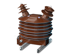
Current instrument bushing transformer
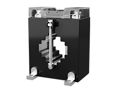
CTB 25
The CTB 25 current instrument transformers are designed for measuring and protecting switchgear in indoor configurations for system maximum voltages up to 25 kV.
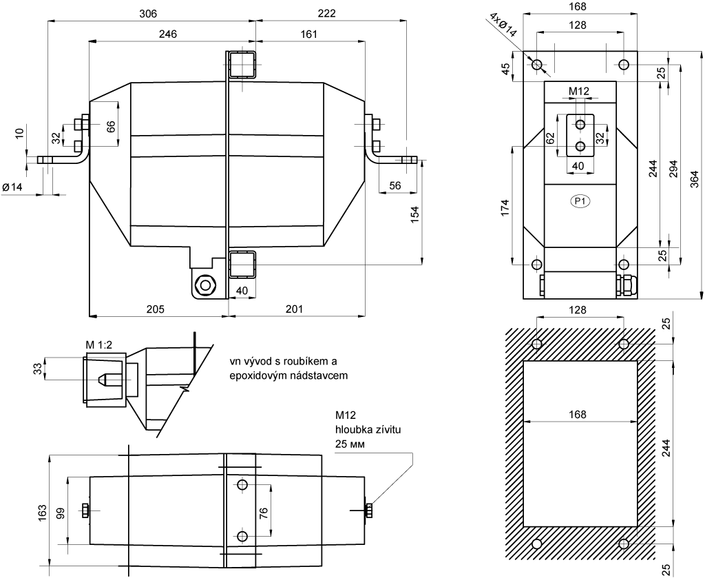
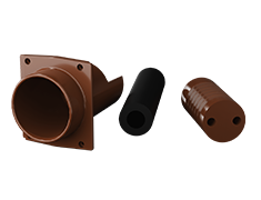
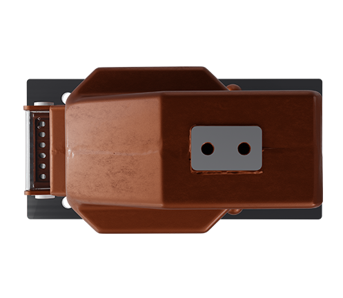
For connecting to the busbars along the longitudinal axis of the device, special brackets with 14 mm diameter holes can be supplied, or alternatively, a bolt with an epoxy bushing.
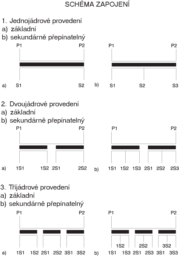
The design of the transformers allows for switching of primary current ranges on the secondary side. The mounting position of the transformers is arbitrary.
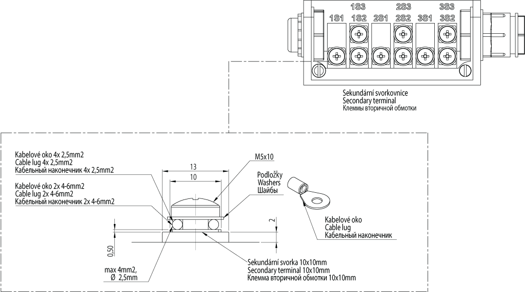
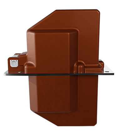
They are secured using four M12 screws through holes in the base plate. For connections to the secondary terminals, it is recommended to use cable lugs according to the conductor cross-section used.
Inquire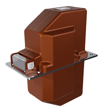
Description
The value of secondary current is 5 A or 1 A with the possibility of combination. The accuracy classes for the circuits of measurement are 0.2, 0.5, 0.2S, 0.5S, 1, 3, for the circuits of protection are 5P, 10P and PX. The transformers fulfill the required accuracy class at intervals from 25 % to 100 % of rated load.
The terminal working current is 120 % IN, in case of the agreement of the producer and the customer it is possible to deliver also the other values, for example 200% IN.
Transformers CTB 25 are designed as passaging, where the primary conductor is made by two and more windings, according to the required parameters. The primary terminals of transformers are equipped with the screws. The special parts with the holes of diameter of 14 mm, eventually pin with epoxy adapter (see dimensional sketch), can be supplied for the connection of lead – in passes along the horizontal axis of the instrument.
The secondary winding is wound on the magnetic core made of directed plates, eventually made of the alloy of nickel, iron and copper (“permalloy”). The maximum number of cores can be from 1 to 3 according to the request of customer and according to the required parameters. The construction of transformers allows the switching of ranges of the primary current on the secondary side.
All active parts of transformer are compound-insulated with epoxy-mixture. This material performs both the electrical insulating and the mechanical functions.
The mounting position of transformers is arbitrary. Transformers are fixed by the means of four screws M12 in the holes in the basic plate. We recommend use terminal ends corresponding to the used cross-section of the conductor for attaching to the secondary outlets.
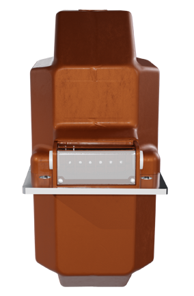
The secondary terminal plate is equipped with cover with sealing screw. Inside, there is the set with jumpers and small screws for the possibility of earth connection and short circuiting of the wiring. (See “The Instructions for the mounting and operation”).
Transformers CTB 25 fulfilled all the tests according to the IEC 61869-1, IEC 61869-2.
For the customer’s request we provide official calibration.
It is possible to consult other technical parameters with the producer.
Parameters
- Highest voltage for equipment: 24/25 kV
- Power frequency test voltage: 50 kV
- Lightning impulse test voltage: 125 kV
- Nominal primary current: 5–1250 A
- Nominal secondary current: 5 A or 1 A
- Rated short-time thermal current, Ith: max 31.5 kA/1s
- Rated dynamic current, ldyn: max 66 kA
- Rated continuous thermal current, Icth: 120 % In
- Accuracy class–measurement: 0.2S, 0.2, 0.5S, 0.5, 1, 3
- Overcurrent factor–measurement: FS 5, FS 10
- Accuracy class–protection: 5P, 10P, PX
- Overcurrent factor–protection: 5, 10, 15, 20, 25, 30
- Nominal power: 5–60 VA
- Nominal frequency: 50 Hz
- Weight: 27 kg
- Thermal insulation class: E
- Operating temperature: corresponds to temperature class -5/40 according to IEC 61869-1
- Standard: IEC 61869-1, IEC 61869-2
Drawing