Medium-voltage instrument transformers

Instrument transformers product line CTS with voltage detection
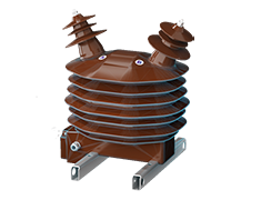
CTS
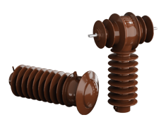
Instrument transformers CTS12, CTS 25 and CTS25X can be equipped with voltage detector hv. On principle it is made by coupling capacity (capacitor divider) which is moulded in epoxy machine casting. A voltage detector is connected to this by a special cable.
Inquire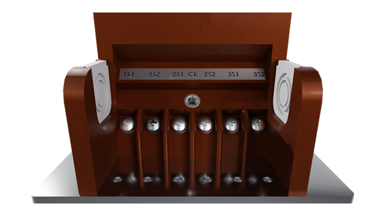
Description
Instrument transformers CTS12, CTS 25 and CTS25X can be equipped with voltage detector hv. On principle it is made by coupling capacity (capacitor divider) which is moulded in epoxy machine casting. A voltage detector is connected to this by a special cable.
The function is determined by norm ČSN EN 61243-5. Voltage indication absent (detector’s LCD display is empty) is in the primary voltage area smaller than 10 % Rv (where Rv is voltage system that is e.g. 6, 10, 15, 22 kV). Voltage system present (you can see letter “U” on LCD display) has to be in the area where primary voltage is higher than 45 % Rv. In the area from 10 % to 45 % Rv, the voltage indication present can be (but does not have to be) alight.
The VDS (voltage detection system) of HR class (high resistance) has been chosen for transformers CTS. Wiring (so-called “interface”) and other accessories (panel and detector) are made by GEORG JORDAN GMBH producer. The system has been put through exams according to ČSN EN 61243 and it is being delivered as a set.
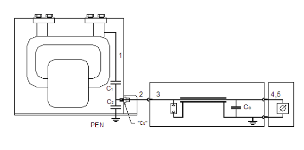
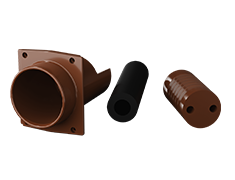
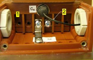
The system description (mounting procedure) is clear from figure 1.
It consists of measuring transformer No. 1. There is a capacitator divider inside made by coupling (high-voltage) capacity C1 and low-voltage capacity C2. Reading voltage is brought out to the terminal Ck which is placed in device’s secondary terminal board. It differs from other terminal by thread M6. The terminal of contact cable No. 2 is screwed into this (the follow-through force is determined by the slide of plastic terminal in metal tightening wrench. Its opposite end is plugged into cable interface connector No. 3. The end of cable interface is then plugged into isolated terminal on detector panel No. 4. Earthing terminal of interface is plugged into earthing terminal of panel as in figure No. 4. Detector No. 5 is plugged into appropriate sockets as in figure 4.
The system can be used within the temperature interval of -25 °+ 50 °C in internal environment. Cable No. 3 can be 3 m or 6 m long.
You have to specify the detector requirement, the length of cable and rated line voltage in the order: e.g.: transformer CTS 25X with voltage detector, system voltage 22 kV, cable of interface 6 m.
Instrument transformers CTS 12 are equipped by the indication within the range of voltage 6–15 kV.
Instrument transformers CTS 25 and CTS 25X are equipped by the indication within the range of voltage 15–22 kV.
Parameters
- Nominal frequency: 50 Hz
- Thermal insulation class: E
- Operation conditions: corresponds to temperature class -5/40 according to IEC 61869-1
- Standard: ČSN EN 61869-1, ČSN EN 61869-2, IEC 61869-1, IEC 61869-2, GOST 15 150
Drawing